Alternate methods to pipe a buffer tank
Common arrangements for buffer tanks.
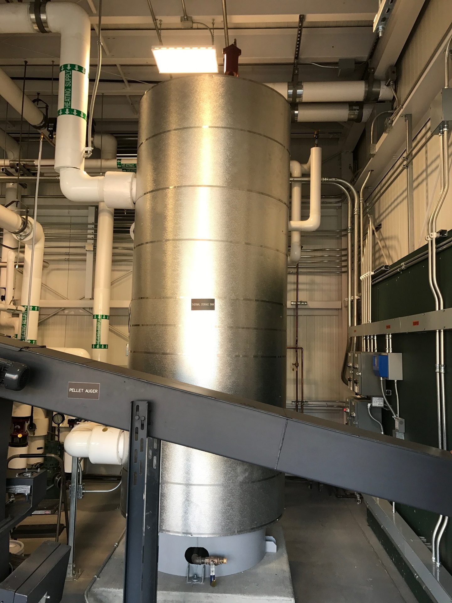
Short operating cycles continue to be one of the chronic complaints associated with modern hydronic heat sources. Even state-of-the-art mod/con boilers with 5:1, 8:1 or even 10:1 ratios between their maximum firing rate and minimum stable firing rate can’t always match the heating load imposed by a single small zone, such as a towel warmer radiator in the master bathroom, on a mild day. This is where the additional thermal mass provided by a buffer tank provides the “thermal elasticity” needed between heat supply and heat demand.
Over the last couple of decades, the North American hydronics industry has been learning the importance of buffer tanks as low thermal mass boilers, and water-to-water heat pumps have been increasingly combined with highly zoned distribution systems.
As biomass-fueled boilers make their mark on the industry, one of the principles most system designers now agree on is that a properly sized buffer tank is essential to good performance for wood-gasification boilers, as well as boilers fueled by pellets and wood chips.
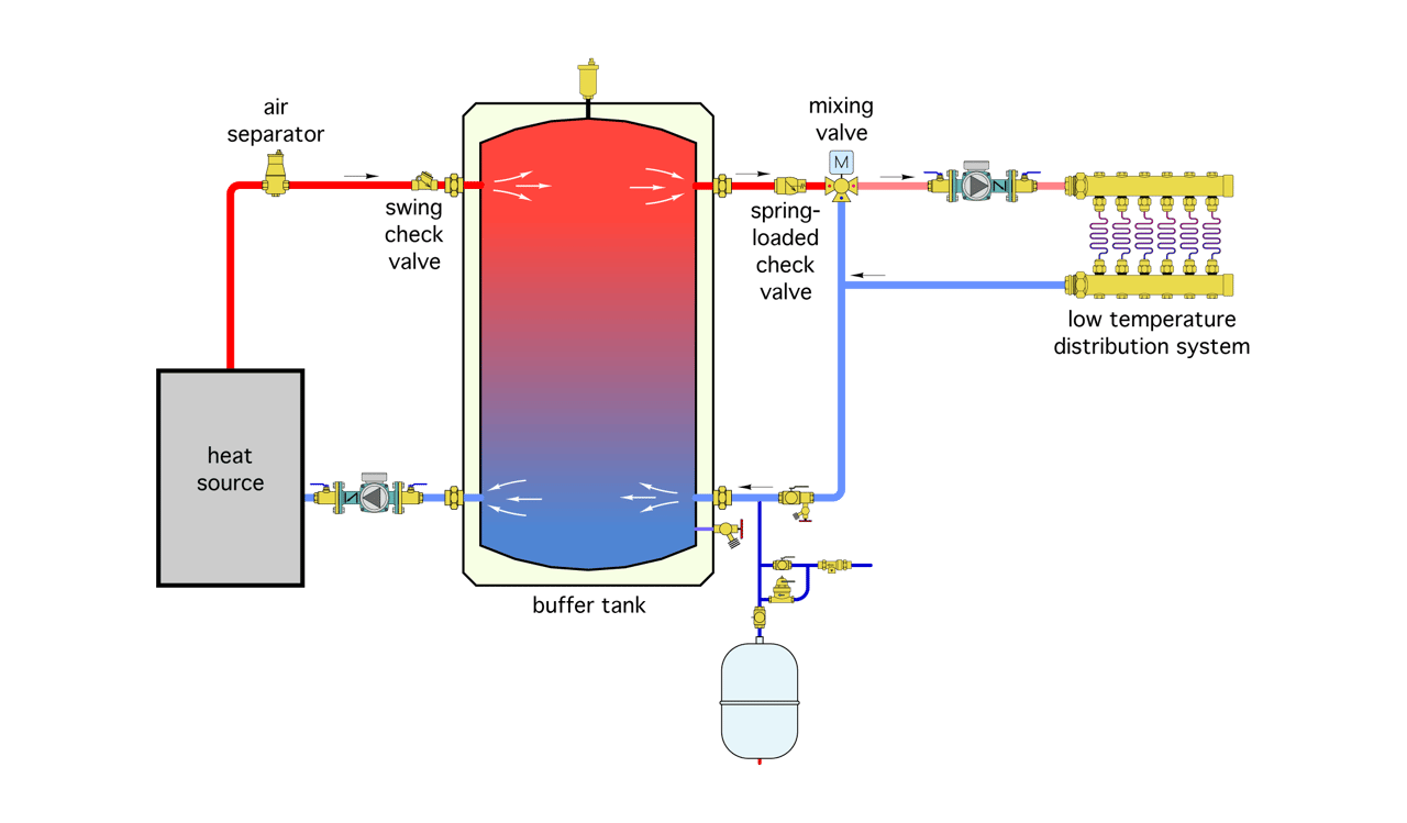
In North America, one of the most common arrangements for a buffer tank is to install it between the heat source and distribution system, as shown in Figure 1.
ENLARGE
FIGURE 1
The “hot” water from the heat source enters an upper side wall connection on the tank. Water headed for the distribution system exists from another upper side wall connection. Because this water is hotter than the water in the tank, it is slightly less dense, and thus remains in the upper portion of the tank. When the flow rate into the distribution system is about equal to the flow entering the tank from the heat source, the entering hot water tends to “slide” across the upper portion of the tank and doesn’t disturb the cooler water in lower portions of the tank.
Notice that a swing check is shown on the pipe leading into the tank from the heat source. Its purpose is to stop reverse thermosiphoning during times when the tank contains heated water but the heat source is not operating. The upper right connection leading from the tank to the distribution system also contains a check valve. I suggest a spring-loaded check valve here to stop potential forward thermosiphoning when the distribution system is not operating. A swing check does not have sufficient forward opening resistance to stop such thermosiphoning.
A similar situation occurs in the lower portion of the tank. Cooler water returning from the distribution system tends to remain in the lower portion of the tank and slide across to the bottom left sidewall connection back to the heat source. These effects are desirable because they maintain temperature stratification in the tank.
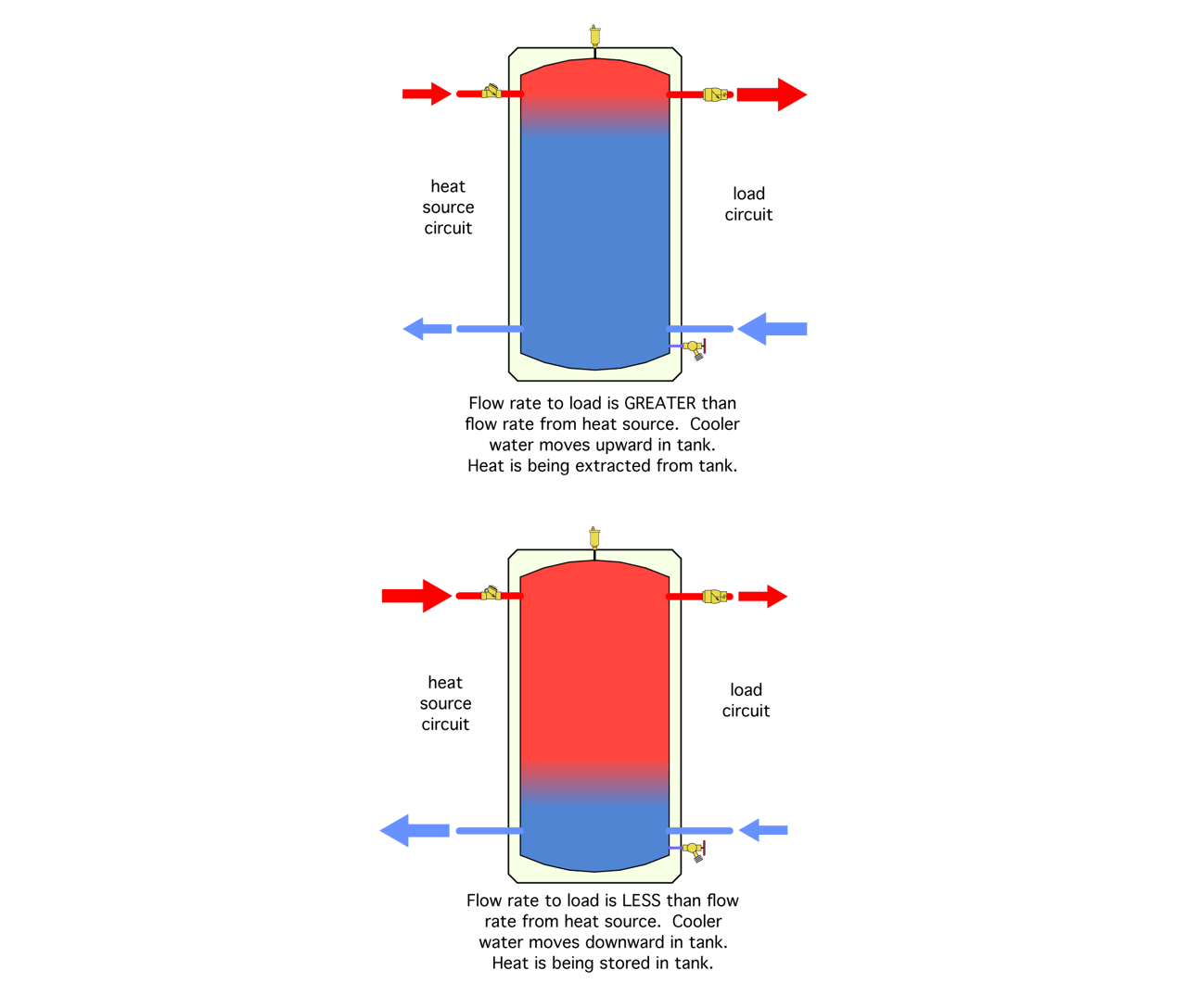
If the flow in the distribution system is greater than the flow entering the tank from the heat source, cooler water will begin to migrate upward in the tank. The tank is giving up heat to the load under this condition. If the entering hot water flow rate is greater than the flow leading to the distribution system, hot water will begin to migrate downward in the tank. The average tank temperature increases as the surplus output of the heat source is stored. The tank is taking on heat under this condition. Both of these conditions are shown in Figure 2.
ENLARGE
FIGURE 2
Additional benefits
Besides providing thermal storage that allows reasonably long operating cycles of the heat source, a buffer tank piped as shown in Figure 1 also provides excellent hydraulic separation between the heat source circuit and load circuit. This happens because the internal flow velocities within the tank are very low compared to the flow velocities in the piping connections to and from the tank. There is almost zero head loss across the tank, or from the top to the bottom of the tank, due to these low velocities.
The low flow velocities also allow dirt particles that may be present in the flow returning from the distribution system to drop to the bottom of the tank. The only problem is most buffer tanks are not designed to efficiently flush out dirt that settles to the bottom of the tank. Dirt that happens to settle near the drain valve may get entrained with flow out the bottom tank drain, but the low local flow velocities in other lower areas of the tank cannot effectively entrain dirt and, thus, are unable to carry it to the drain connection.
As such, most buffer tanks can eventually separate and accumulate dirt, but are not good at ridding the system of that dirt. This is why a modern dirt separator, which can generate sufficient internal flow velocity during a flush to entrain any accumulated dirt, is the preferred choice.
The heat stored in a buffer tank also can be used for domestic water heating or preheating, using either an internal coil heat exchanger suspended in the upper portion of the tank or the on-demand assembly shown in Figure 3. We’ve discussed the latter in several previous columns. It’s an excellent way to harvest heat from any thermal storage tank.

ENLARGE
FIGURE 3
Downstream tank
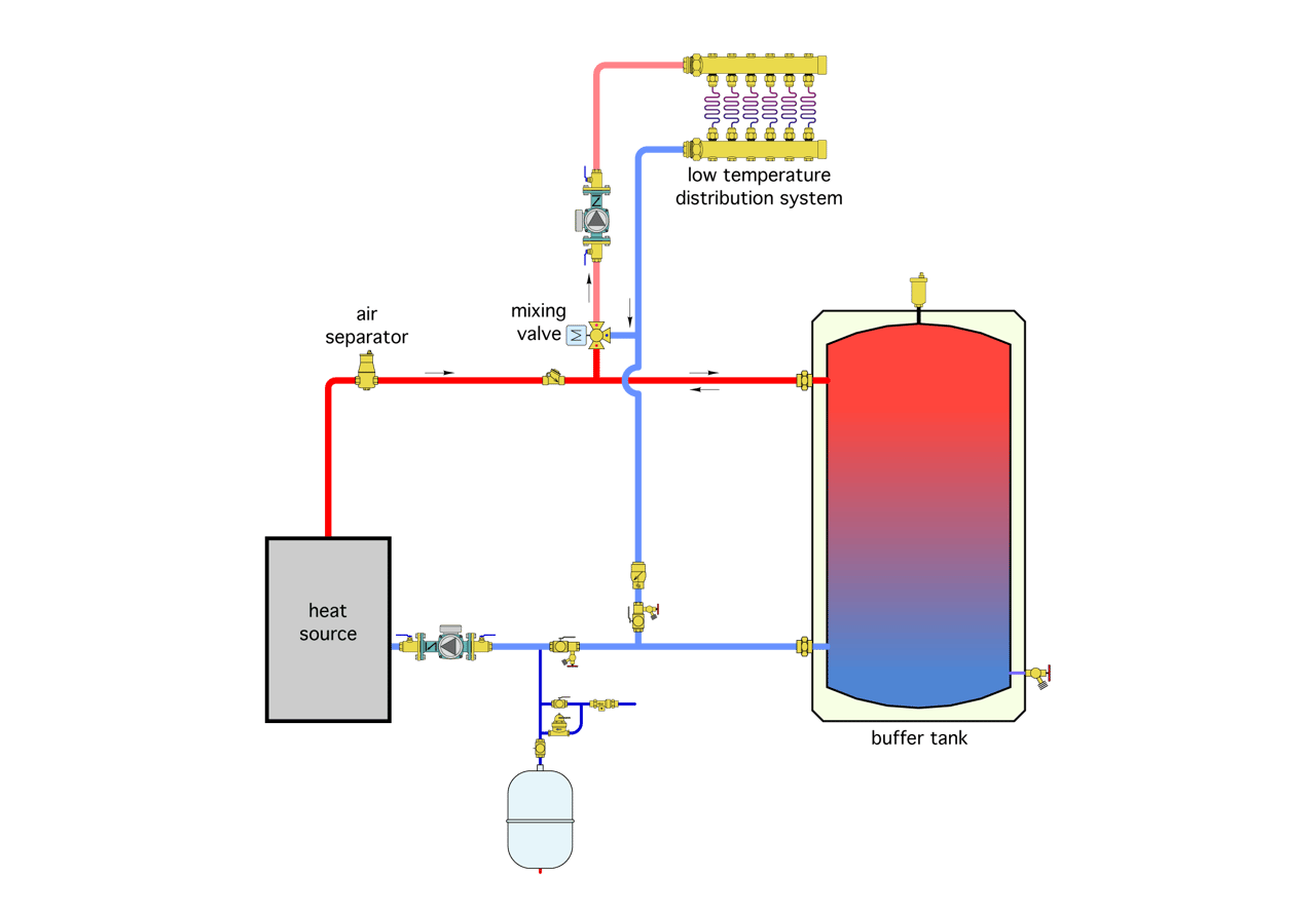
After looking over many schematics from European sources, especially those associated with biomass boilers, I’ve noticed a trend that places the buffer in a slightly different arrangement relative to the heat source and load. This alternate arrangement is shown in Figure 4.
ENLARGE
FIGURE 4
In this layout, flow from the heat source doesn’t pass through the buffer tank on its way to the distribution system. Instead, the distribution system extracts heat from the piping between the buffer tank and heat source. Any hot water flow from the heat source that isn’t pulled off into the distribution system passes downstream into the buffer tank. If the heat source is off, stored hot water from the buffer tank flows backward and then into the distribution system.
It’s also possible for some flow to enter the distribution system from the heat source, while the remainder of the required flow comes from the buffer tank. This happens when the distribution system requires more flow than is currently passing through the heat source.
One possible benefit of this arrangement is the distribution has access to the hottest water in the system before that water passes through the upper portion of the buffer tank. This would be an advantage if the buffer tank was allowed to significantly cool down over several hours before the next call of heat occurs. Under such a condition, the tank would have to be substantially reheated to bring it back to temperatures suitable for the distribution system.
Although such operating conditions might be possible in certain installations, standby heat loss from the tank should always be minimized by using very generous insulation and providing piping details that stop thermosiphoning.
The piping shown in Figure 4 also eliminates two of the sidewall connections on the buffer tank. This might open up some possibilities, depending on the tank selections available. However, in my opinion, it’s better to have more connections than necessary and either plug them off if not needed or use them for other purposes — such as sensor wells, thermometers, sight gauge connections or piping connections — that better match incoming flows to the likely temperature stratification of the tank. Extra connections might also be used to accommodate the on-demand DHW assembly shown in Figure 3.
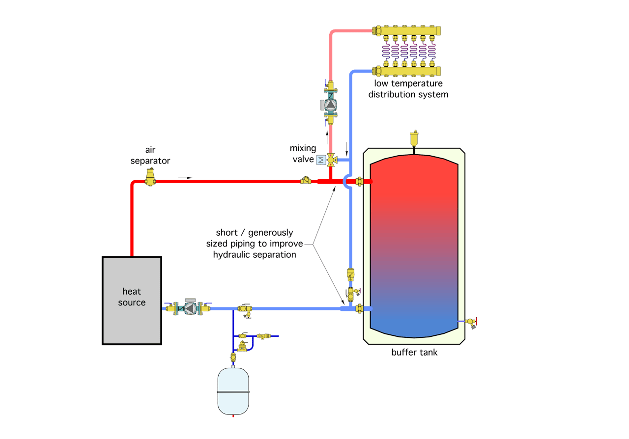
The degree of hydraulic sedation between the distribution circulator and heat source circulator provided by the system in Figure 4 would depend on the length and size of piping between the tees where the distribution subsystem connects the piping connections to the tank. This piping should be short and generously sized to minimize head loss, as shown in Figure 5. Notice that both check valves are still used to prevent thermosiphoning through the heat source when it’s inactive, or through the distribution piping.
ENLARGE
FIGURE 5
Even with the details shown in Figure 5, I think the arrangement shown in Figure 1 provides better hydraulic separation since it eliminates the head loss associated with the tees connecting the distribution system to the piping between the heat source and tank, and any piping between these tees and the tank. This higher degree of hydraulic separation would be especially desirable if the distribution circulator(s) operated at variable speeds.
Either the traditional buffer tank piping shown in Figure 1 or the alternate method shown in Figure 5 can be used. Both have been used on many successful installations. It’s likely to come down to what tanks are available, how the piping connections on the tank are sized and located, and how those tanks would be optimally located in relationship to the other components and subsystems.
Images and figures courtesy of John Siegenthaler.
This article was originally published in Plumbing & Mechanical in OCTOBER 2014.