Creating multiple water temperatures in hydronic heating systems
Various ways to provide multiple water temperatures from a single heat source.
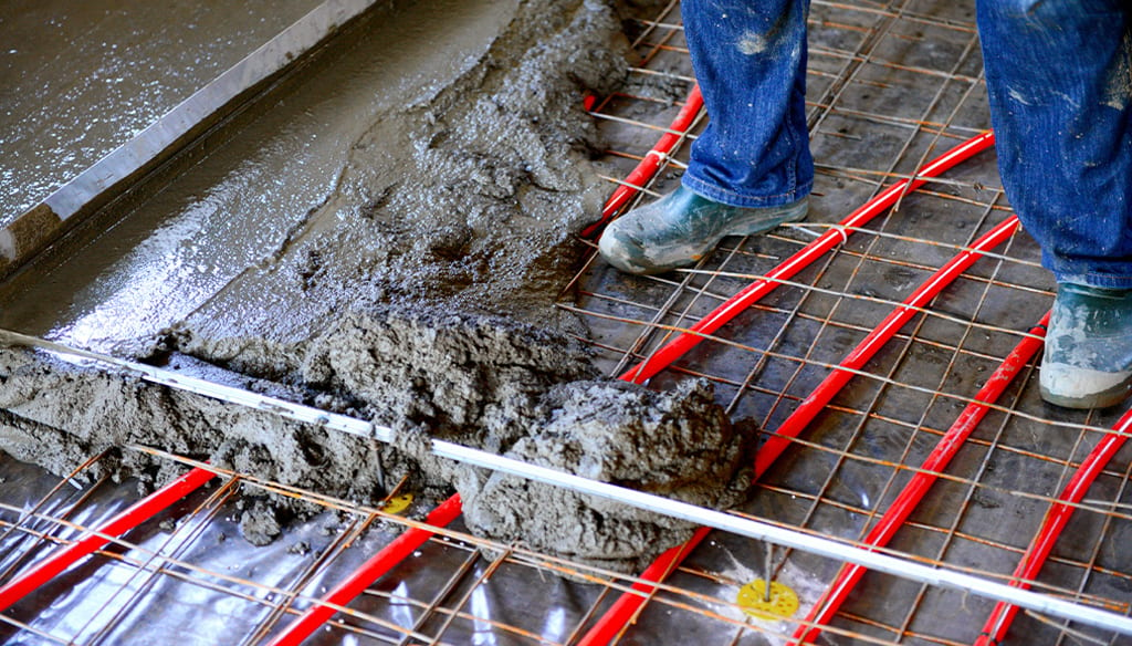
Many hydronic heating systems use two or more types of heat emitters that require different water temperatures to be supplied simultaneously. For example, one part of the building may be heated by tubing embedded in a concrete floor slab, while another portion is heated by fin-tube baseboard or panel radiators. These two subsystems can have significantly different supply temperature requirements that must be simultaneously provided by the system.
There are several ways to provide multiple water temperatures from a single heat source. These include use of multiple “intelligent” mixing assemblies, as well as a technique known as submixing, which uses one intelligent mixing assembly along with one or more “dumb” mixing valves. This article will discuss the strengths and weaknesses of both approaches.
ENLARGE
FIGURE 1
Straight from the heat source
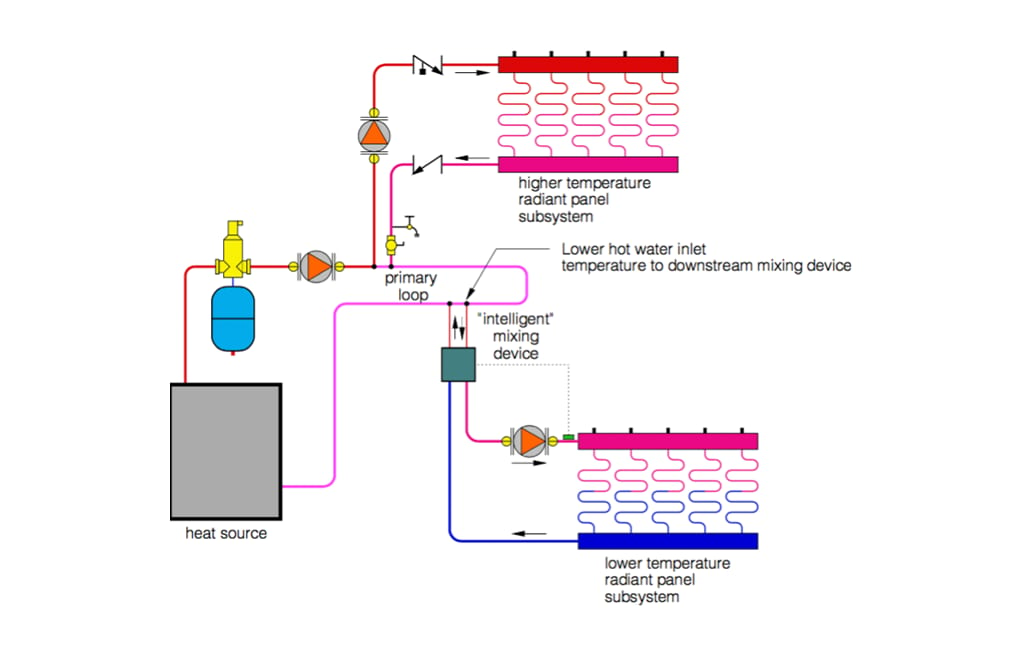
If one subsystem requires water at the same temperature as delivered by the heat source, that subsystem does not require a mixing device. It can be connected directly to the primary loop as a secondary circuit. The lower supply temperature for the other subsystem can be provided through a mixing device. That device may be one of several types of mixing valves or an injection pump. Assuming the mixing device can operate with a hot water inlet temperature a few degrees lower than the primary loop temperature, it can be connected to the primary loop in series with the other load, as shown in Figure 1.
ENLARGE
FIGURE 2
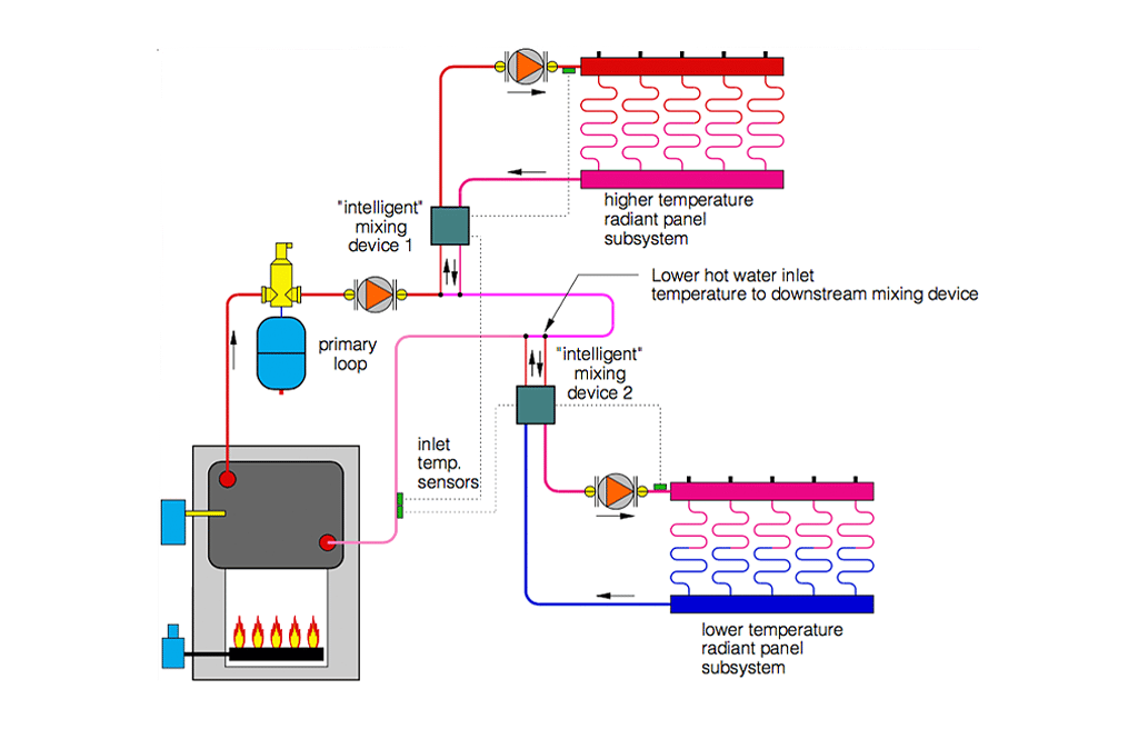
If both subsystems require supply temperatures lower than the operating temperature of the primary loop, two mixing assemblies are required. This approach is more common when a conventional boiler is used as the heat source.
One approach is to use two independently controlled “intelligent” mixing assemblies. Examples include motorized mixing valves or variable speed injection pumps. If a conventional boiler is used, each mixing device should be configured to provide inlet temperature protection to prevent sustained flue gas condensation. Such an arrangement allows either subsystem to operate totally independent of the other. This concept is shown in Figure 2.
ENLARGE
FIGURE 3
Cascading temperatures
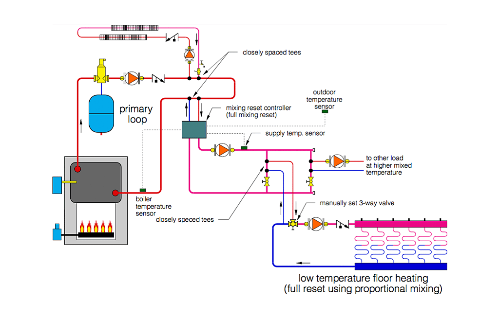
Another approach, one that’s often overlooked, is to use “submixing.” In this approach, one “intelligent” mixing device supplies the highest of the necessary mixed supply temperatures, while other “dumb” mixing devices further reduce supply temperatures in other parts of the system.
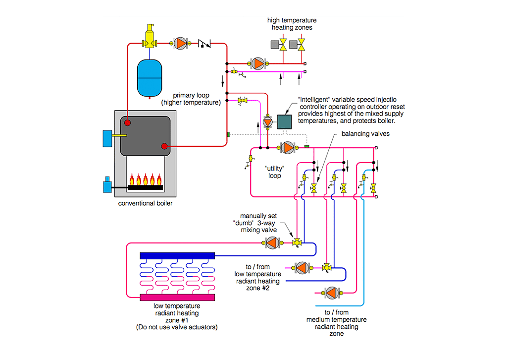
An arrangement capable of providing two mixed temperatures, as well as a high temperature load, is shown in Figure 3.
Submixing allows multiple water temperatures to be created at a lower cost than when multiple intelligent mixing devices are used.
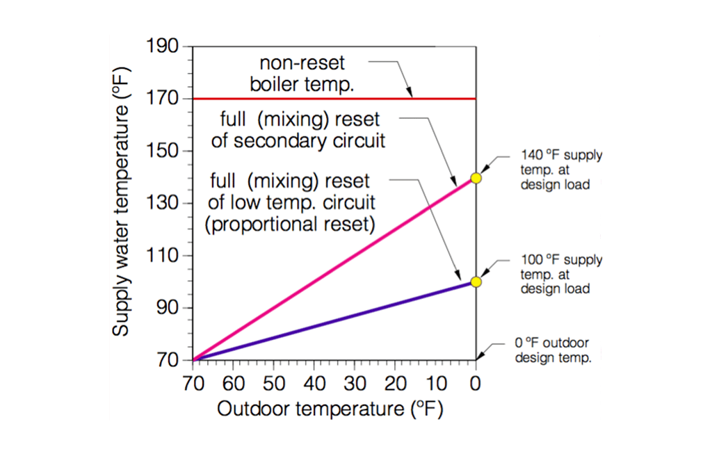
When the “intelligent” mixing device varies the higher mixed water temperature using outdoor reset control, the lower mixed temperatures also track along a reset line. This effect is called proportional reset and is illustrated in Figure 4.
ENLARGE
FIGURE 4
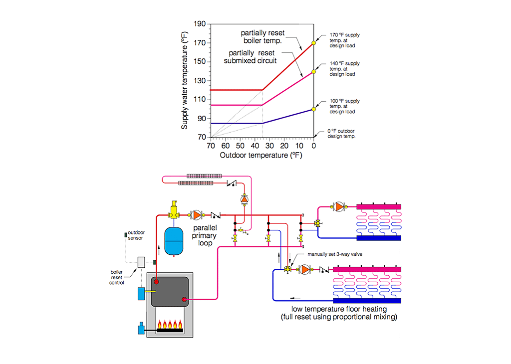
Notice that the lower reset line passes through a supply temperature of 100° F at the assumed outdoor design temperature of 0° F. The upper reset line indicates a supply temperature of 140° F at the same outdoor temperature. If the higher of the two water temperatures is only partially reset due to minimum boiler temperature requirements, the lower reset line will also be partially reset. Both lines transition from sloping to flat at the same outdoor temperature. At outside temperatures above this value, flow through the high temperature and low-temperature subsystems must be cycled on and off to prevent overheating. Such a situation is illustrated in Figure 5.
ENLARGE
FIGURE 5
The concept of proportional reset can be extended to produce more than two fully reset or partially reset supply temperatures. In every case, the highest water temperature would be controlled by a reset control, and the lower water temperatures created by simple manually set mixing valves. The system shown in Figure 6 is an example.
ENLARGE
FIGURE 6
Limitations of submixing
There are limitations that must be evaluated when considering submixing:
- Since any manually set mixing valve (e.g. a “dumb” valve) only provides fixed flow proportions of the incoming water streams, any variation in the temperature or flow rate of either stream causes a change in the mixed water temperature. Unlike an intelligent mixing device, a “dumb” mixing valve cannot compensate for such changing inlet conditions.
For example, consider a system in which zone valves are installed for individual circuit control. Whenever a zone valve opens or closes, the flow and head loss of the distribution system changes. This causes a corresponding change in the flow proportions at the dumb mixing device and a change in the mixed outlet temperature. Under some conditions, there could be wide variations in the mixed temperature. - Submixing with a manually set mixing valve is generally not a good idea for spaces that have frequent changes in thermostat settings, especially if that space is heated by a high thermal mass radiant panel. Such an installation could experience long recovery times following a setback because the mixed temperature supplied to the circuits would be depressed by the cooler than normal temperature returning from the radiant panel circuit. An intelligent mixing device could compensate for this. A dumb device cannot.
- A dumb mixing device cannot protect a conventional boiler from low temperature operation. When such a device supplies a low temperature/high thermal mass radiant panel, it should only be used downstream of an intelligent mixing device that senses boiler inlet temperature and can limit heat transfer to the distribution system when necessary.
ENLARGE
FIGURE 7
The concept at work
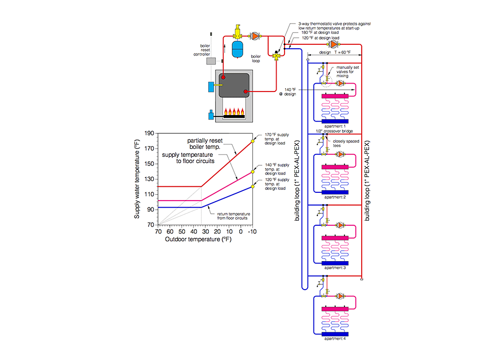
The piping schematic shown in Figure 7 is for a system installed in an apartment building. The designer used a boiler with outdoor reset control to supply water through a parallel primary loop that passed down the center hallway of the building. A reverse return piping layout, along with equally sized crossover bridges, was used to make the primary loop self-balancing. At design load conditions, each crossover supplies 180° F water to a set of injection risers for each apartment. Manually set two-way valves provided the mixing to achieve a supply temperature of 140° F to the floor circuits at an outdoor design temperature of -10 degrees F. As the outdoor temperature warms, the boiler reset control reduces the temperature in the primary loop. Submixing provides proportional reset of the water temperature to the floor heating circuits.
Since a conventional boiler is used, partial reset is used to protect the boiler from flue gas condensation. On/off operation of the circulator in each apartment is used to prevent overheating. On mild but damp days in spring and fall, the fact that the water temperature is slightly higher than it would be with full reset control allows a more rapid response of the system when occupants turn up the thermostat. If necessary, the supply temperature to individual apartments can also be varied by adjusting the pair of two-way valves serving as the mixing device.
This system is a good example of how submixing can provide good temperature control and reduce installation cost.
ENLARGE
FIGURE 8
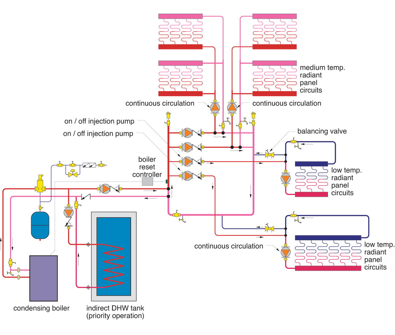
Another example of submixing is shown in Figure 8. This system uses a condensing boiler to supply radiant floor heating as well as indirect domestic hot water.
The condensing boiler is operated by an outdoor reset control that determines the proper supply temperature of the higher temperature radiant floor circuits based on outdoor temperature.
Submixing is used to further reduce supply temperature to two manifold stations that operate at lower temperatures. In this case, the submixing is done using two on/off injection pumps — one for each of two lower temperature manifold stations. When one of these manifolds requires heat input, the associated injection pump is turned on. A balancing valve is used to set the injection flow rate to the design load condition. This arrangement also allows for continuous flow in all radiant circuits.
ENLARGE
FIGURE 9
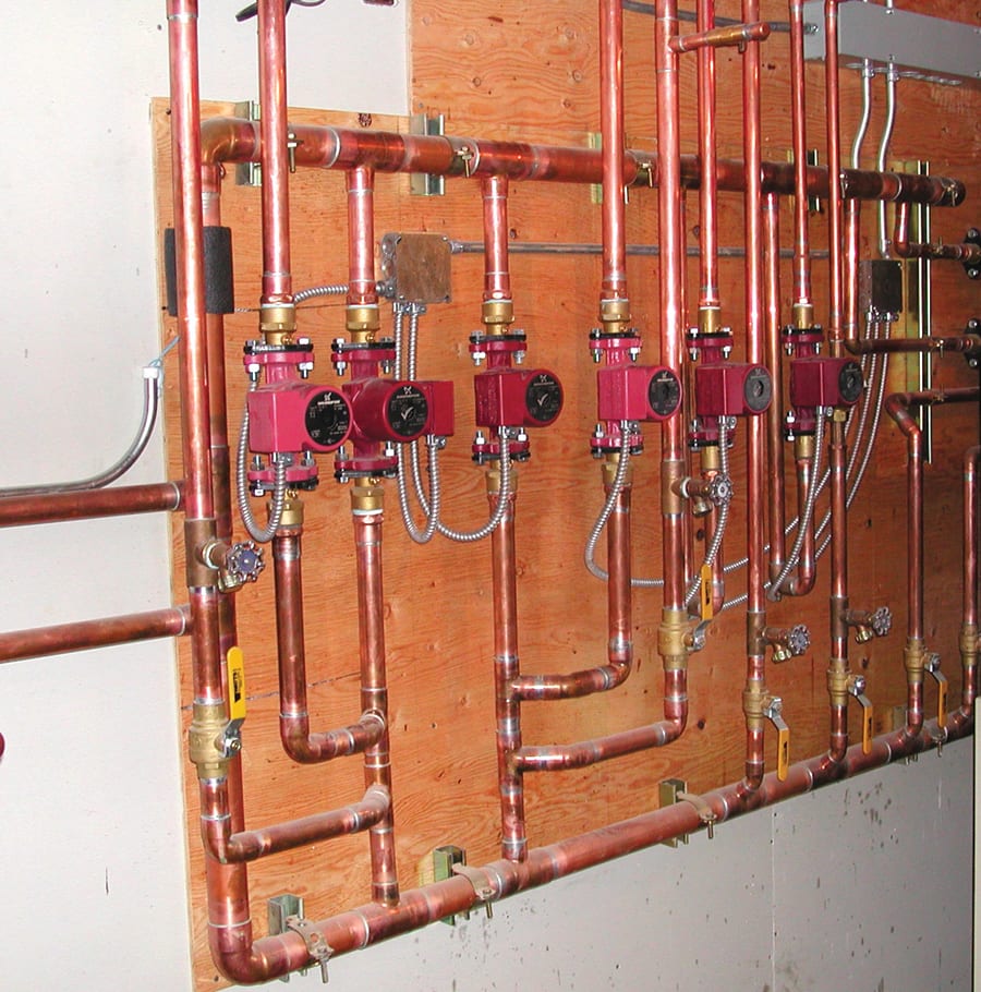
During the domestic water heating mode, the boiler is allowed to climb to its upper limit setting (180° F). The transfer circulator between the boiler and spacing heating circuits is turned off, and the circulator leading to the indirect tank is turned on. The system is now in a priority domestic water heating mode. The only “intelligent” controller in this system is the single boiler reset control. A portion of the system piping is shown in Figure 9.
Summary
Submixing and proportional reset are presently underutilized in the hydronics industry. When properly applied, they can reduce the cost of the control/mixing hardware necessary to deliver the benefits of reset control in multiple water temperature systems.
elenaleonova/iStock / Getty Images Plus via Getty Images. Figures courtesy of John Siegenthaler.
This article was originally published in PM Engineer in June 2003.