Beyond closely spaced tees
Several products that extol the virtues of primary/secondary piping.
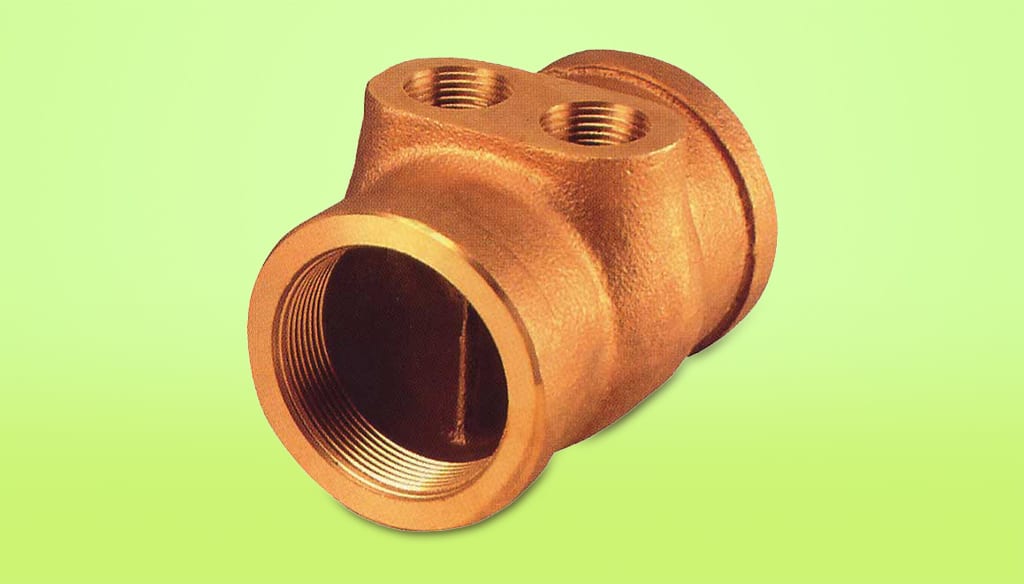
In past columns we’ve discussed primary/secondary piping many times. The key detail has been a pair of closely spaced tees that couple the secondary circuit to the primary loop in such that flow in the primary loop has very little tendency to induce flow in the secondary circuit.
The wide spread acceptance of P/S piping has created market demand for products that optimize the concept while also speeding the installation. Several such products have appeared on the North American market over the last couple of years to address this demand. This month we’ll look at several of them.
A product for parallel primaries
Series primary loops are well suited to situations where two or more secondary loads will operate with different supply temperatures. The basic idea is pretty simple: Connect the higher-temperature loads near the beginning of the primary loop and the lower-temperature loads near the end. This arrangement tends to increase the temperature drop along the primary loop, which reduces the flow rate. It may also decrease the size of the piping and circulator for the primary loop.
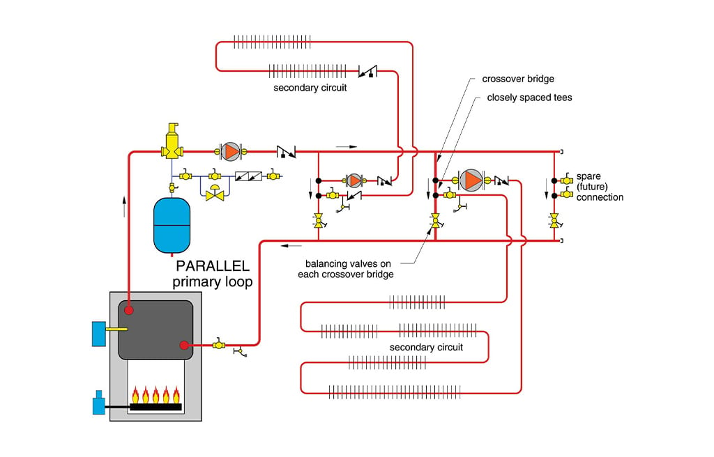
However, when a system has several secondary circuits that need to operate at approximately the same supply temperature, they should connect to a parallel primary loop as shown in Figure 1.
ENLARGE
FIGURE 1
Parallel primary loops are more expensive and time-consuming to build than are series primary loops. Given the advantages they offer, you would think that someone would come up with a way to reduce the time and cost associated with building a parallel primary loop. Turns out, someone has.
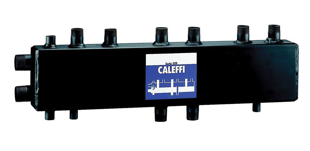
The manifold shown in Figure 2 is from Caleffi North America. It’s a prefabricated means of achieving the pump isolation and equal supply temperature benefits of a parallel primary loop.
ENLARGE
FIGURE 2
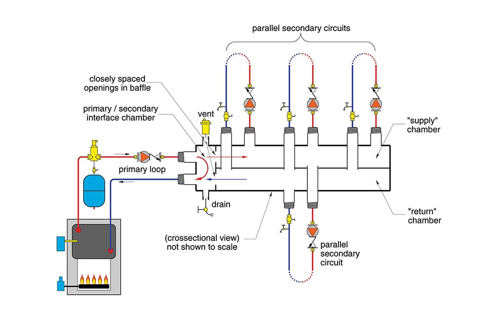
A typical piping arrangement using this manifold is shown in Figure 3.
ENLARGE
FIGURE 3
The boiler loop circulator is responsible for moving water through the small chamber on the left side of the manifold. This chamber has a common wall with the internal header chambers on the right side. Two closely spaced openings through this wall in effect represent two closely spaced tees.
Because the openings are so close together, there is almost no pressure difference between them. Thus the pressure differential across the internal headers on the right side (from supply to return) is close to zero. The pressure increase created by a given zone circulator is almost entirely “spent” by the time the flow makes it back to the return manifold. This arrangement prevents interference between the boiler circulator and whatever zone circulators are operating. It’s the same concept that keeps the peace between circulators in a typical primary/secondary system.
If the total flow rate of the zone circulators exceeds the primary loop flow rate, there will be a flow reversal between the closely spaced openings. This is not a problem. It leads to a mixed supply temperature to the zone circuits.
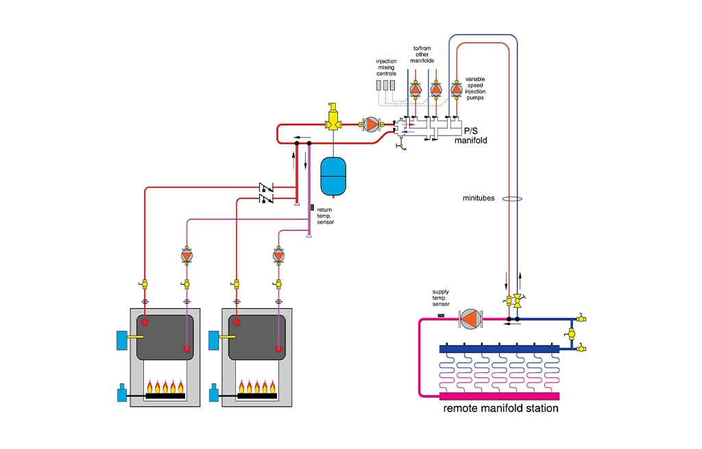
Figure 4 shows how this manifold could be used for a multiple-zone minitube injection system. In this application, the P/S manifold supplies several variable-speed injection pumps, one for each remote manifold station. This arrangement is possible because the extremely small pressure differential in the header will not induce injection flow in any given circuit until that circuit’s injection pump is operating.
ENLARGE
FIGURE 4
The manifold also has tappings for an air vent and drain. It provides a clever and compact alternative to traditional parallel primary loop construction.
Closely coordinated
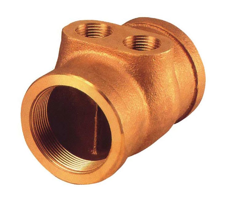
There are other recently released products that capitalize on the advantages of primary/secondary piping. One comes from Taco Corp. in the form of a special LoadMatch™ fitting as shown in Figure 5.
ENLARGE
FIGURE 5
This fitting provides the closely spaced supply and return ports for a secondary circuit. It uses a vertical baffle to split the flow path between the left and right secondary circuit ports to prevent recirculation. Because the two ports are side by side rather than one in front of the other, they are at exactly the same dynamic pressure. No flow will be induced in the secondary circuit until the secondary circulator operates.
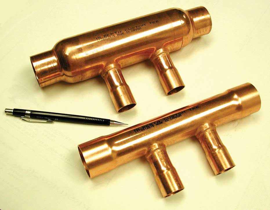
Another offering comes from Alberta Custom Tee Ltd. The specially fabricated fitting, shown in Figure 6, provides the closely spaced secondary ports on a single fitting. It is available in different tube size combinations, with and without an enlarged primary run diameter. The enlarged diameter reduces flow velocity (not flow rate) between the side ports. In theory, this further reduces the already small pressure drop between these ports.
ENLARGE
FIGURE 6
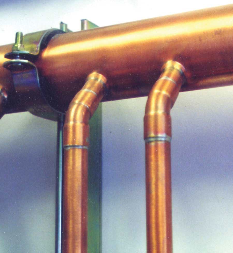
Of course, if you happen to own a T-Drill® and know how to braze, you can make the equivalent of two closely spaced tees as shown in Figure 7. These connections supply a variable-speed injection pump from a 2 1/2-inch copper primary loop. They are simple, clean and surely less expensive than installing a couple of 2 1/2-inch copper tees and reducer fittings.
ENLARGE
FIGURE 7
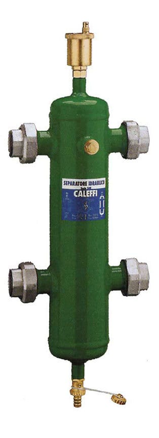
Another product from Caleffi North America is called a “hydraulic separator,” and is shown in Figure 8
ENLARGE
FIGURE 8
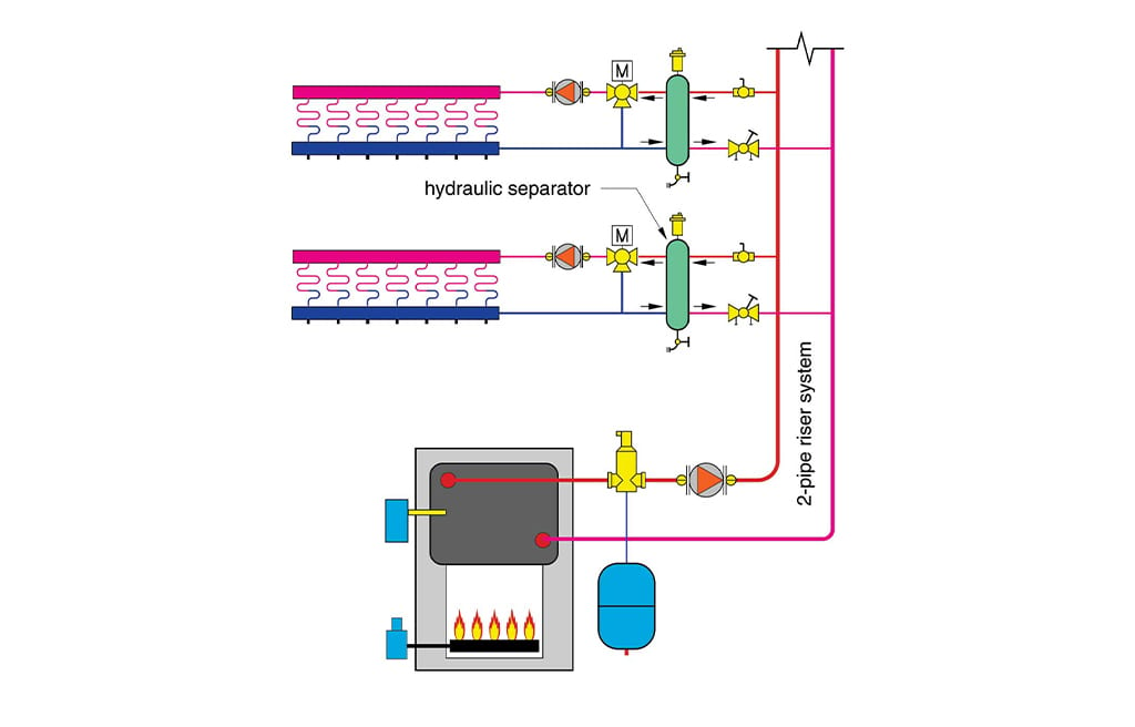
This device can be used to uncouple the pressure distribution of a typical two-pipe riser system from that of individual zone distribution circuits as shown in Figure 9. The diameter of the vertical chamber relative to that of the piping slows the vertical flow velocity.
ENLARGE
FIGURE 9
There is virtually no pressure drop from top to bottom. Thus, the chamber acts similar to a pair of closely spaced tees to prevent interference between the two-pipe riser system and individual zone circuits. The reduced flow velocity also allows air bubbles carried into the device to rise and be ejected through the vent. Particulates carried into the chamber can also settle out and be purged through the drain valve at the bottom.
All these devices use the same fluid mechanic principles as a pair of closely spaced conventional tees. They provide unique and timesaving ways to take advantage of those principles. Check them out for some of your upcoming projects.
Courtesy of Caleffi North America, Taco, Alberta Custom Tee Ltd., T-Drill and Caleffi North America. Figure drawings courtesy of John Siegenthaler.
This article was originally published in Plumbing & Mechanical in June 2003.