bulletin | feature
Discrete element modeling deepens understanding of microcracking phenomena in refractory materials
A new discrete element method provides a deeper understanding of the relationship between a refractory’s microstructure and its macroscopic thermomechanical properties—paving the way to use microcrack engineering for commercial refractory production.
By Harikeshava Ranganathan, Damien André, Marc Huger, Ratana Soth, and Christoph Wöhrmeyer
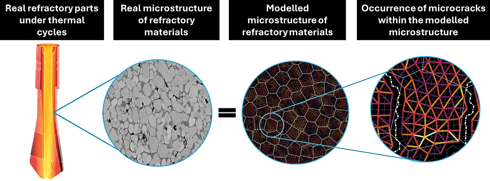
Schematic diagram showing the link between real microstructures and discrete element modeling.
Images reproduced with permission from Reference 1 and www.vesuvius.com. Descriptive captions provided by Damien André.
Credit: Mouiya et al., Journal of the American Ceramic Society; www.vesuvius.com
Though defects are often associated with weakening mechanical properties, the purposeful introduction of microcracks into refractory materials can improve their thermal shock resistance.
Refractories are heterogeneous materials, consisting of numerous aggregates within a brittle matrix.1,2 Microcracking occurs during synthesis when the refractory is cooled from its sintering temperature due to the heterogeneity and anisotropy of thermal expansion coefficients of each constituent.3,4 The presence of numerous microcracks within the microstructure can promote a significant nonlinear macroscopic mechanical response, which improves the material’s resistance to thermal shock.1,3,4
Improved thermal shock resistance is a desirable property for refractories in steel making, cement making, glass processing, and other high-temperature industries. However, the relationship between a refractory’s microstructure and its macroscopic thermomechanical properties is complex, and deeper understanding of this relationship is needed to enable the use of microcrack engineering for commercial production.
As part of the European Union-funded CESAREF project, the authors developed a novel discrete element method (DEM) to deepen understanding of the refractory microstructure–property relationship. The development, testing, and prospects for this tool are described in the following sections.
ADVERTISEMENT

Background: Numerical methods for modeling the refractory microstructure–property relationship
Numerical modeling is a vast field with different numerical approaches. Many researchers have used the finite element method (FEM), which breaks down complex systems into smaller elements for analysis, to comprehend the mechanics of bulk materials for high-temperature applications.5 However, FEM’s limitations include its computational time-consuming nature due to dynamic meshing and its difficulty in analyzing fractures without considering preexisting crack location, path, and growth at the microstructure level.
The extended finite element method (XFEM) was introduced as an improvement on FEM due to its ability to describe discontinuities without mesh refining.6 However, this approach, unlike FEM, does not allow researchers to capture nucleation of multiple microcracks. Additionally, it is difficult to depict the opening and closing of microcracks at the microstructure level.
Phase-field modeling (PFM) was introduced as another method to investigate multiple crack nucleation, propagation, and branching behaviors at the microstructure level. While PFM shares some similar concepts with FEM, it relies on different criterion for the simulation. For this reason, PFM can accurately replicate crack morphology of experimental tests, but model discrepancies may lead to unrealistic crack growth in simulations due to difficulties in capturing the complete microstructure characteristics.7
These limitations with the above continuum approaches led researchers to start using DEM for refractory applications. Initially, DEM was used to investigate the free flow of granular particles from a silo or hopper.8 Later, DEM was adopted for performing thermomechanical simulations on a cohesive medium.8,9 Today, DEM is seen as an advanced numerical technique that can be used to perform multiphysics, multiscale, and quasi-brittle analysis for cohesive mediums.2,10,11
Unlike FEM, XFEM, and PFM, which represent systems as a single continuum, DEM represents bodies as discrete particles. These particles interact with their neighbors according to contact interaction laws,8,9 which state that microscale interactions result in emergent properties that can be measured on the macroscale as an apparent property.11–13 As such, DEM offers significant potential for modeling microstructures with numerous discontinuities, such as inclusions, cracks, debonding, and porosity, as seen in many refractory microstructures.
Previously, researchers used DEM with contact models between spherical discrete elements for investigating the relationship between the refractory microstructure and the macroscopic thermomechanical properties.14–16 The current study instead uses polyhedral discrete elements, as described in Reference 14, to investigate this relationship. Similar to Reference 14, the phases in the model are assumed to be chemically inert, and the presences of interphases are negligible in the model microstructure.
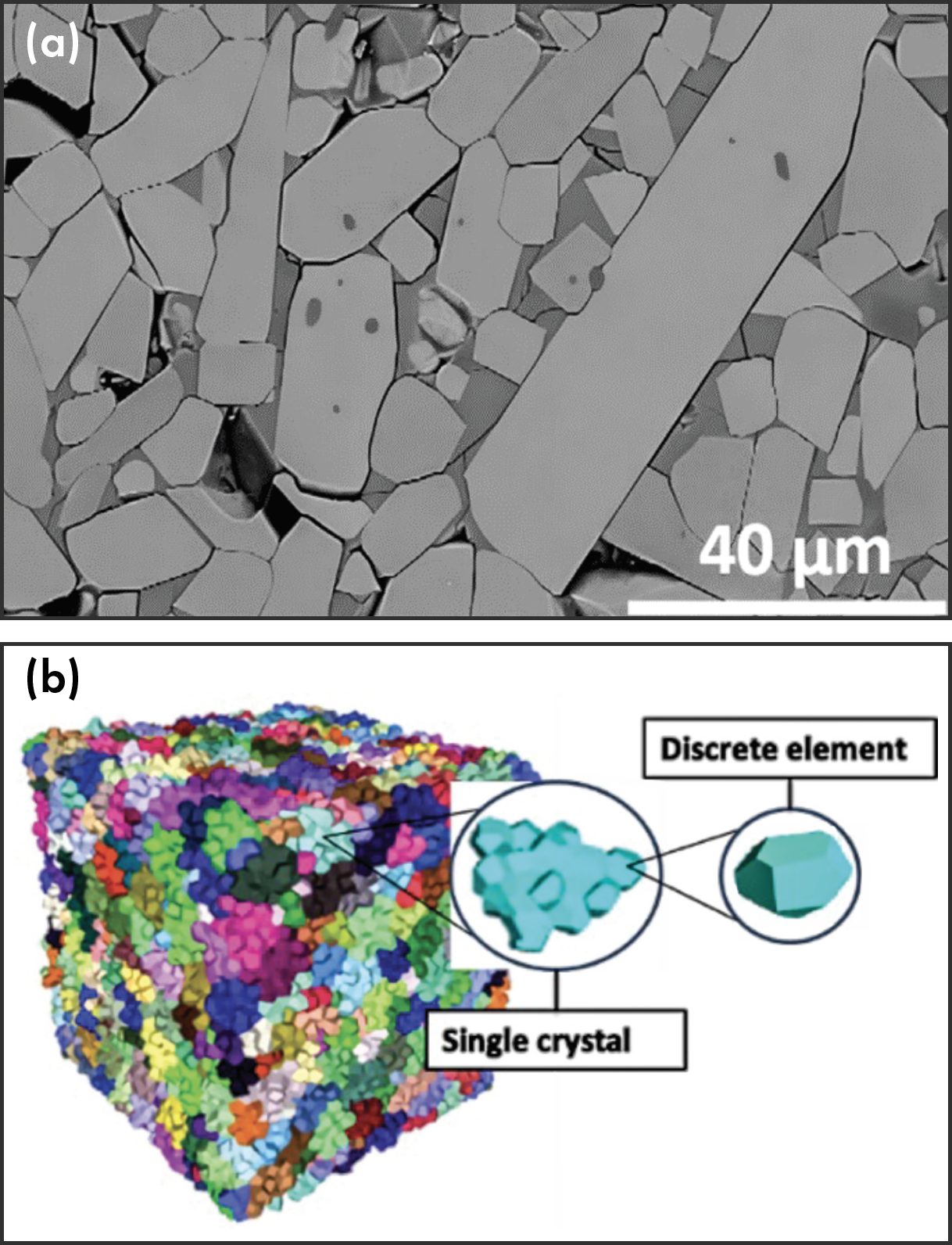
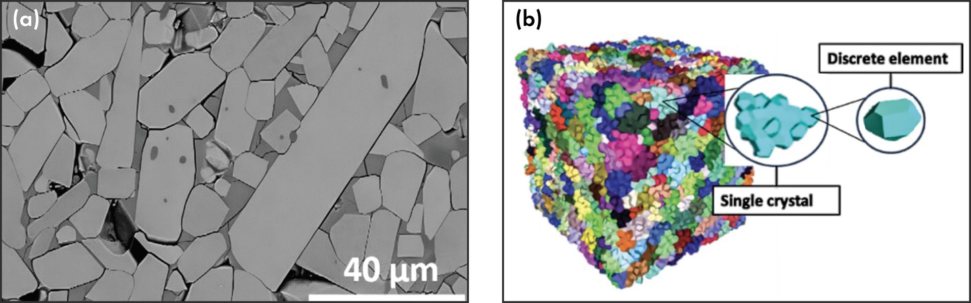
Figure 1. The real microstructure1 (a) and DEM model (b) of aluminum titanate, which was used as the reference material in this study.
Credit: a) Mouiya et al., Journal of the American Ceramic Society; b) Ranganathan
Numerical procedure
Reference model material: Polycrystalline aluminum titanate
Polycrystalline aluminum titanate (Figure 1a, above) was chosen as the reference material because the numerous microcracks within its microstructure lead to a very low thermal expansion and high thermal shock resistance.1
These microcracks result from high anisotropic thermal expansion coefficients of the individual grains, which generate internal stresses within the microstructure during the cooling stage right after sintering.1,4 The resulting microcracked microstructure, after complete cooling, promotes a significant quasi-brittle behavior in tension.
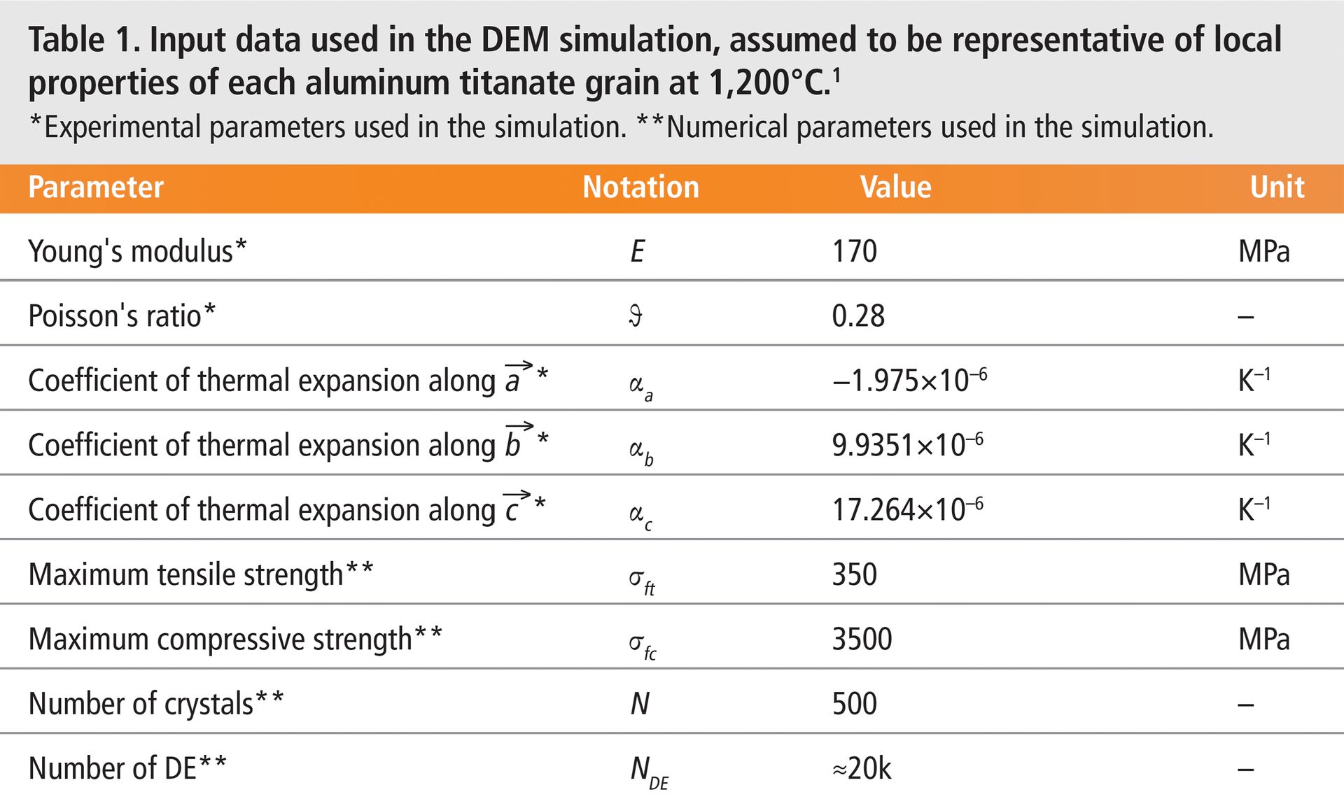
The DEM model aimed to qualitatively reproduce this tensile behavior (microcracks nucleation and their influences on the macroscopic mechanical properties), which is typical in many industrial refractory materials.1 The simulation is performed with GranOO, an opensource discrete element workbench. The input data used in this DEM simulation, which represent local properties of each aluminum titanate grain at 1,200°C, are summarized in Table 1 below.
The DEM numerical sample is a box with dimensions of 100 μm × 100 μm × 100 μm to mimic the bulk cohesive medium. Each crystal in the numerical sample is assigned a random orientation, which is depicted by the crystal having different colors (Figure 1b), and they are built by assembling about 40 polyhedral discrete elements of random sizes. The polyhedral discrete elements are assigned the physical, mechanical, and thermal properties given in Table 1. The model is imposed with the elastic brittle law and local failure criteria.
Lattice spring model and Voronoi tessellation
The DEM introduces discrete element interactions into the simulation through so-called contact models. In literature, many contact models exist: dual spring model,16 flat-joint,12 and cohesive beam,13 to name a few. Among them, the lattice spring model (LSM) is an advanced contact model because of its ability to deal directly with continuous mechanical properties, such as stress and strain. In this aspect, fastidious calibration steps can be avoided with LSM, and material thermomechanical properties, such as Young’s modulus (E), Poisson’s ratio (ϑ), and coefficient of thermal expansion (α), can be directly introduced in the model.
However, this introduction is possible only if the interaction surfaces between the discrete elements are equivalent to a continuum medium without voids. So, to obtain a domain equivalent to a continuum medium, a plane-sweeping algorithm called a Voronoi tessellation is processed on the dedicated domain.
In a Voronoi tessellation, several points scattered on a plane are subdivided into exactly n cells that enclose a portion of the plane closest to each point. To generate scattered points for the tessellation, transitory spherical discrete elements (in a predefined range of size) are filled in the domain, as shown in Figure 2a. The centroids of the transitory spherical discrete elements are used as input for the Voronoi tessellation to generate polyhedral elements. These polyhedral discrete elements are connected using contacts (yellow line in Figure 2a, below) generated by a Delaunay tessellation. So, the process to generate the DEM model (with LSM) involves dual tessellation. For more details about the fundamental aspects of the LSM contact model, readers can refer to Reference 9.
The current study uses LSM as the contact model in the DEM simulation. Additionally, this simulation can handle anisotropic thermal expansion thanks to the inclusion of periodic boundary conditions within the simulation.
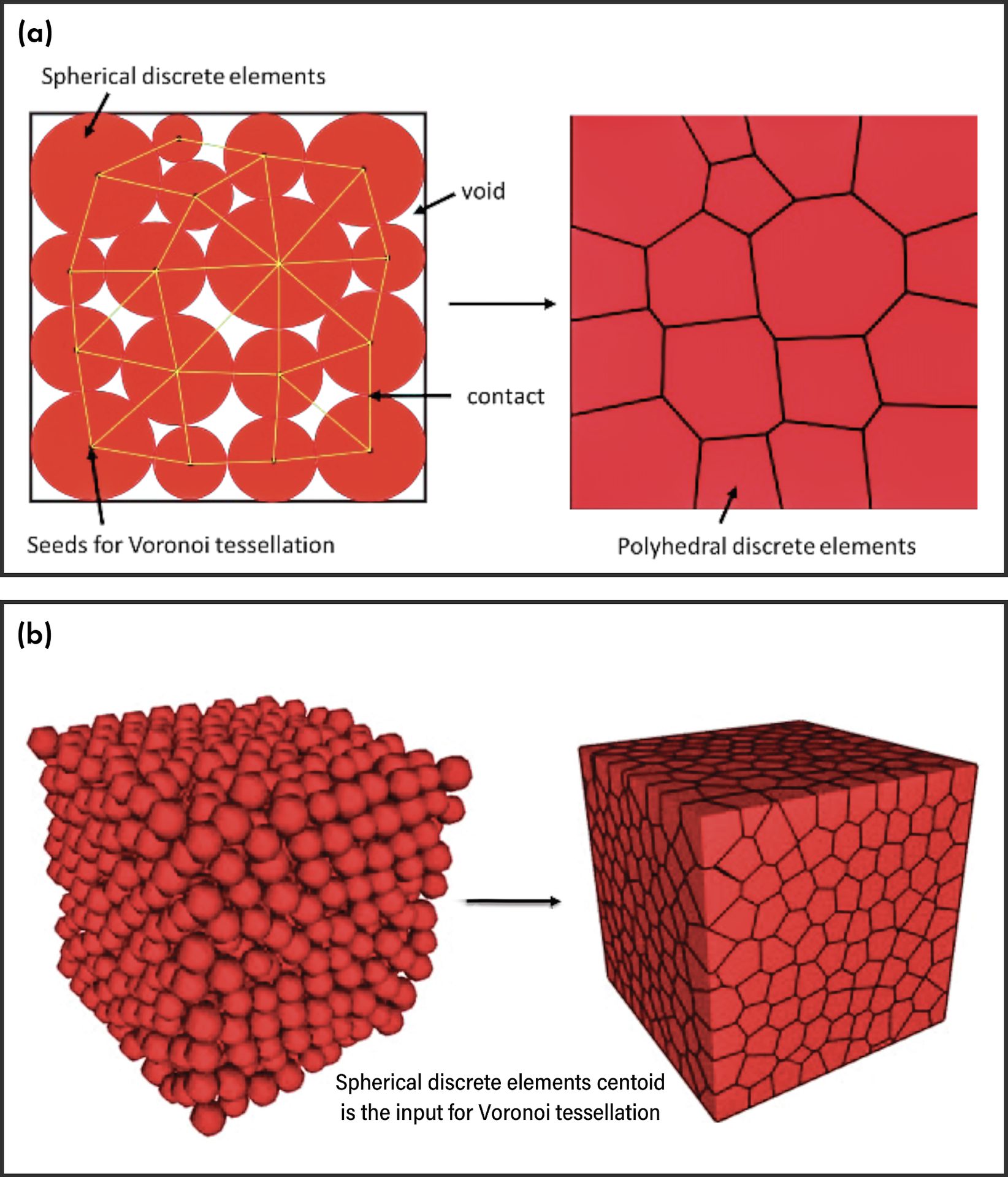
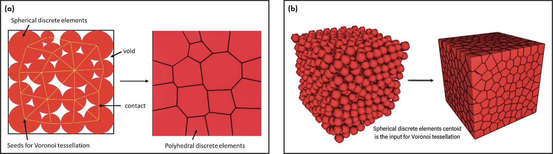
Figure 2. The Voronoi tessellation process: a) 2D sketch and b) 3D view with discrete elements.
Credit: Ranganathan
Periodic boundary conditions
Periodic boundary conditions, or PBCs, are a well-known concept in the field of homogenization modeling. Homogenization is a numerical technique that can perform multiscale analyzes from the micro- to macroscale by taking advantage of the potential periodicity of the microstructure.
Past researchers have incorporated PBCs into DEM models to introduce an infinite cohesive media using a finite periodic cell (green cell in Figure 3a, below) to replicate the microstructure.12 In this way, the PBC eliminates the boundary surfaces. This study incorporates PBCs for the same reason.
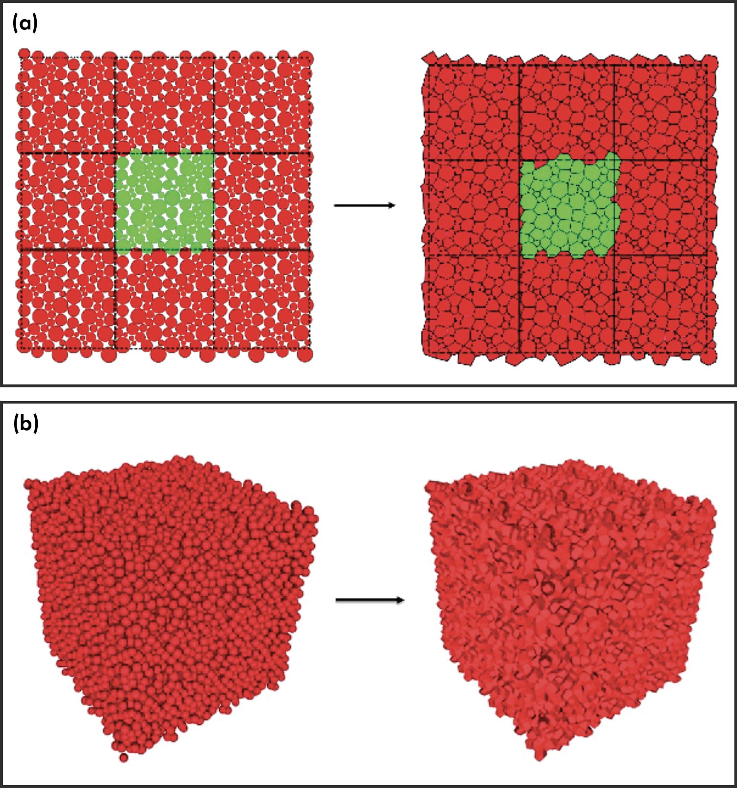
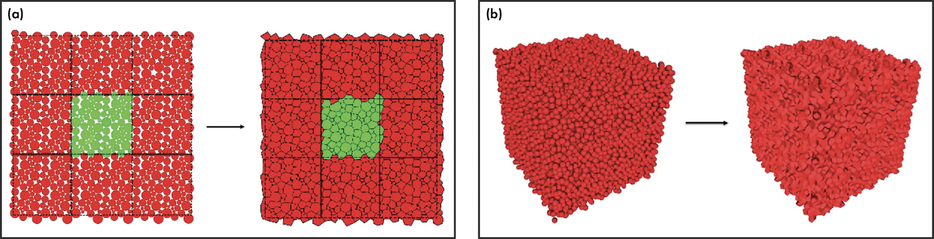
Figure 3. Voronoi tessellation process for periodic boundary conditions:
a) 2D sketch and b) 3D view with discrete elements.
Credit: Ranganathan
Introducing crystals in numerical sample
Each crystal, containing a significant number of discrete elements within the numerical model, should have its own randomly assigned crystal orientation. Again, a Voronoi tessellation is used to define the full crystal geometry. After obtaining the geometry, the Voronoi tessellation is applied as a mask on the periodic polyhedral numerical domain, which was previously obtained. This process allows each aluminum titanate crystal to be defined as a cluster of discrete elements (Figure 4, below). Then, a numerical sample with N grains are generated using the Voronoi tessellation to define the grain boundaries for the polycrystalline numerical sample. The crystals are represented by different colors.
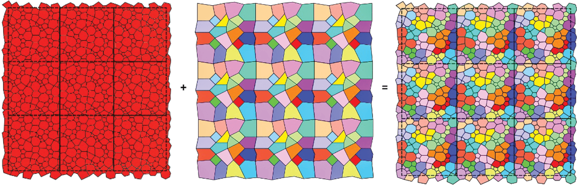
Figure 4. 2D sketch of the numerical polycrystalline representative volume element (RVE), accounting for periodic boundary conditions obtained by Voronoi tessellation.
Credit: Ranganathan
Thermomechanical simulations
The thermomechanical simulation is segregated into two steps. The first step is the cooling process, where the sample is cooled down from 1,200°C to 900°C. During this cooling step, some microcracks are initiated and propagated due to the anisotropic thermal expansion of the crystals. After the cooling stage, the numerical sample with microcracks is obtained. The second step is to perform a uniaxial tensile test on the obtained numerical sample to monitor the macroscopic materials’ mechanical response in terms of strain versus stress evolution (Figure 5).
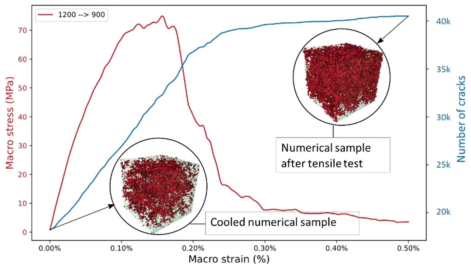
Figure 5. Mechanical response of the numerical sample under uniaxial tensile stress.
Credit: Ranganathan
Discussion
As seen in Figure 5, the microcracked numerical sample exhibits a significant nonlinear mechanical response under tension when cooled from 1,200°C to 900°C. When cooled even further, to 600°C (Figure 6a, below), the sample shows a similar nonlinear mechanical response under tension. On the other hand, in the case of the numerical sample with no microcrack, it exhibits a brittle mechanical response under tensile test (see the 1,200°C curve in Figure 6a).
This difference in the mechanical response supports the claim that the microcracks network strongly influences the thermomechanical properties of the (aluminum titanate) refractory materials. Additionally, the stress–strain curves depict a strong variation from brittle fracture to quasi-brittle behavior depending on the number of preexistent microcracks.1
Similar mechanical responses were observed when microcracked aluminum titanate samples that were cooled down from 1,400°C to 850°C and 20°C were then loaded under tensile test (Figure 6b). The microstructure with no microcracks exhibited a brittle response (Figure 6b at 850°C) and the microstructure with a huge microcracks network exhibited a large nonlinear mechanical response (Figure 6b at 20°C).
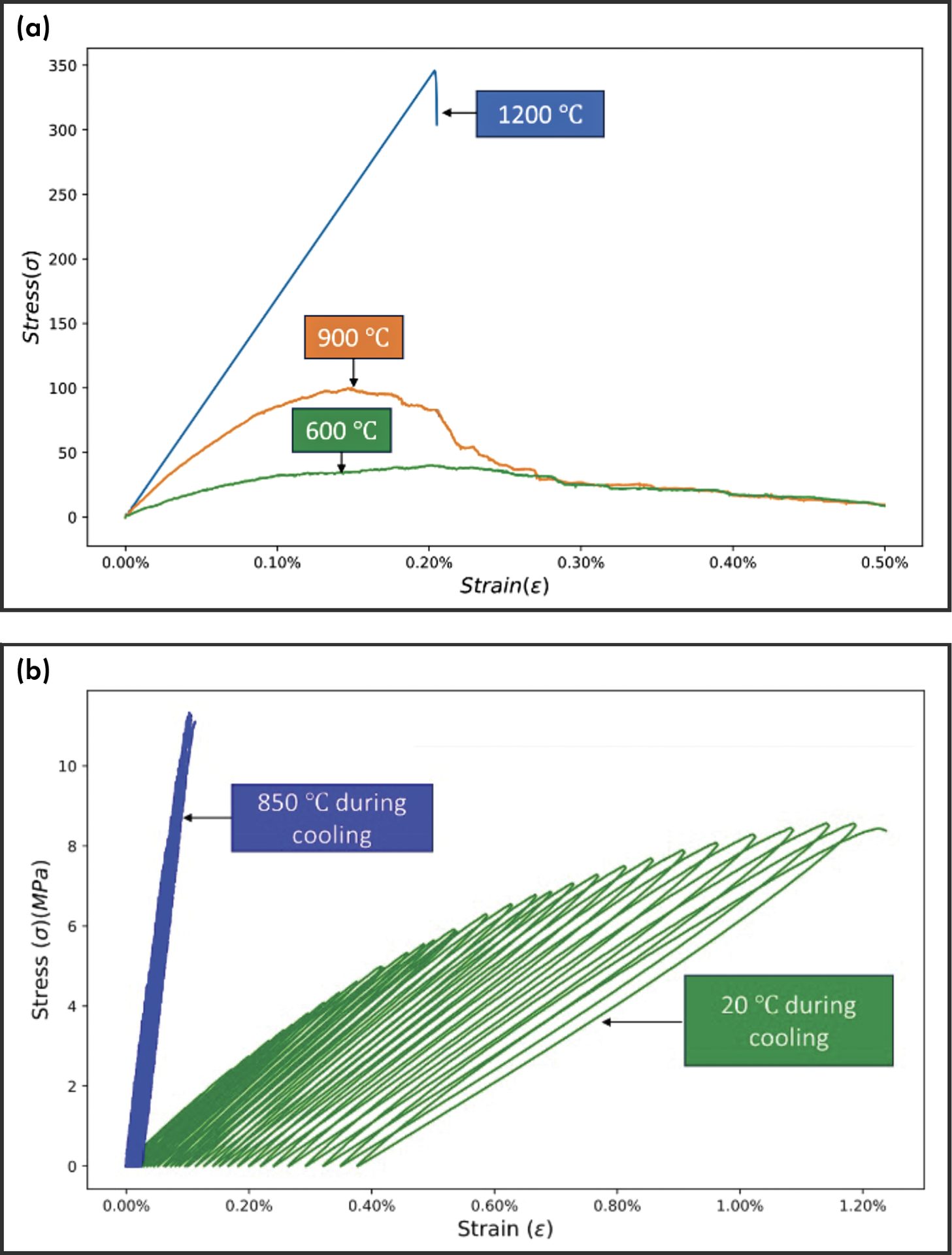
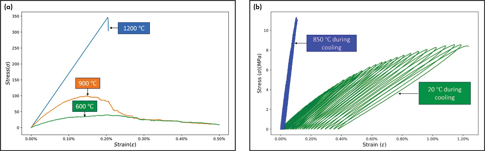
Figure 6. Evolution of the nonlinearity in the stress–strain curve in tension on polycrystalline aluminum titanate materials at different temperatures after a given cooling stage.
a) DEM simulation results at 1,200°C, 900°C, and 600°C (after cooling from 1,200°C).
b) Experimental results at 850°C and 20°C (after cooling from 1,400°C).
Credit: Ranganathan
Conclusion and future directions
To clarify the relationship between microstructure and macroscopic properties in refractory materials, a DEM model was developed and tested using aluminum titanate as a reference. This simulation successfully captured the microcracking phenomena during cooling and then during tensile loading, as well as the macroscopic stress–strain law, demonstrating the potential of DEM models to deepen understanding of the refractory microstructure–property relationship.
In the future, this novel tool could be used to help visualize the evolution of Young’s modulus, Poisson’s ratio, and the coefficient of thermal expansion of aluminum titanate materials versus temperature. First, however, the GranOO platform used in this study should be upgraded so it can capture phenomena such as crack healing mechanisms and crack trajectory mapping. These new data will help the refractory industry to improve on the design of their materials.
About the authors:
Ratana Soth and Christoph Wöhrmeyer are scientist and refractory team lead, respectively, at Imerys Technology Center (Vaulx-Milieu, France). Harikeshava Ranganathan, Damien André, and Marc Huger are Ph.D. student, research associate, and professor, respectively at the University of Limoges, France. Contact Ranganathan, André, or Huger.