bulletin | cover story
Deep decarbonization of glassmaking
Decarbonizing energy-intensive manufacturing processes such as glassmaking requires a mix of strategies across the entire value chain.
By Christopher W. Sinton
At the end of the day, many like to relax with a glass of wine or a bottle of beer. As you open that bottle, you are holding a piece of glass that is responsible for between 60 and 160 grams of CO2 emitted into the atmosphere.1*
In the United States, the government aims to achieve a net-zero greenhouse gas (GHG) emission economy by 2050.2 The U.K. and Europe have the same net-zero goal for 2050, as well as a shorter term goal by 2030 to reduce GHG emissions by 68% and 55%, respectively, compared to 1990 levels.
How does the glass industry reach that goal?
While 2050 may seem decades away—after all, many engineers and researcher working on these problems today will be retired by 2050—the magnitude of the manufacturing process changes and capital investments shift the urgency of acting into a near-term, easily foreseeable timeframe.
For example, “Float glass furnaces typically have a lifespan of 20 years. To meet the 2050 net-zero carbon target, a CO2-neutral furnace must be developed by 2030. Achieving such an ambitious target requires years of development,” says Cyril Jean, R&D portfolio manager at Saint-Gobain Glass.
Significantly reducing the amount of CO2 emissions associated with energy-intensive industries such as the glass industry is paramount to mitigating the effects of climate change. Incremental changes in the glass industry have led to an overall decrease in carbon intensity (kg CO2 emitted per kg of glass made), but a near net-zero or “deep decarbonization” of glass manufacturing is the ultimate goal.
The first step to decarbonization is to account for how much greenhouse gases are emitted by a company across the full manufacturing value chain. Green House Gas Protocol,3 an organization that provides standards, guidance, tools, and training to measure and manage GHG emissions, offers a standardized framework for evaluating the embodied emissions of an entity.
The framework divides an entity’s GHG emissions into three categories or scopes. Scope 1 covers emissions from sources that an entity owns or controls directly, for example, from burning fuel in a furnace. Scope 2 are offsite emissions, such as the electricity purchased and used within the glass manufacturing process. Scope 3 emissions are all GHG sources not within scope 1 and 2 boundaries, including those from sources up and down the value chain, for example, emissions associated with raw material suppliers.
Once the carbon emissions are accounted for, the next step is to develop a strategy to accomplish significant reductions. The U.S. DOE roadmap for industrial decarbonization includes four key technology pillars to significantly reducing carbon emission: energy efficiency; low-carbon fuels/energy sources; industrial electrification; and carbon capture, utilization, and storage (CCUS).4 To this list, we add the glass-specific issue of decarbonizing raw materials. Here we explore each of these areas in detail.
Energy efficiency
Energy efficiency is an important and logical part of decarbonization—less energy from fossil fuel combustion means lower CO2 emissions. Improvements in the energy efficiency of furnaces are the major reason why the carbon intensity of the glass industry has dropped over the decades, as shown in Figure 1 (below). These measures include better furnace and burner design and controls, oxy-fuel firing, and increased post-consumer cullet use.
Oxy-fuel firing can improve the energy efficiency of a furnace by avoiding the nitrogen present in air-fired furnaces and reducing the volume of flue gas. More than 300 commercial glass furnaces worldwide have been converted to oxy-fuel since 1991, including 50 container glass furnaces and 10 float glass furnaces.1 Conversion to oxy-fuel not only reduces NOx emissions, but it also can lead to a 10–20% reduction in energy use depending on whether a heat recovery system is used. Oxy-fuel firing also promotes decarbonization because the resulting flue gas is concentrated in CO2 and amenable to reuse or geologic sequestration (see later discussion).
Raw mineral batch reactions are endothermic, requiring more energy consumption to bring the glass batch to temperature. Using post-consumer cullet eliminates a portion of these endothermic reactions, and energy consumption can be reduced by up to 0.3% for every 1% by weight of cullet in the batch. Additionally, cullet has the added value of having already been processed and is therefore a previously decarbonized raw material.
“Cullet is the key resource for decarbonization of the building glass industry, minimizing our consumption of virgin raw materials and energy and finally reducing the quantities of end-of-life waste generated by the building industry,” according to François Guillemot, low-carbon glass project manager at Saint-Gobain Glass.
Increasing the energy efficiency of existing furnaces is important, but continuing to rely on fossil fuels will not get the industry to the goal of deep decarbonization. The next step is to use a low-carbon energy source.
Low-carbon fuels
The dominant source of CO2 emissions associated with glassmaking is from the energy needed to reach melting temperatures of the raw materials and to maintain the melt for refining. Most glass in the U.S. is produced using natural gas (usually methane) derived from fossil deposits. There are several feasible substitutions for natural gas that are low in fossil carbon or are derived from sources that have no net increase in atmospheric CO2.
ADVERTISEMENT
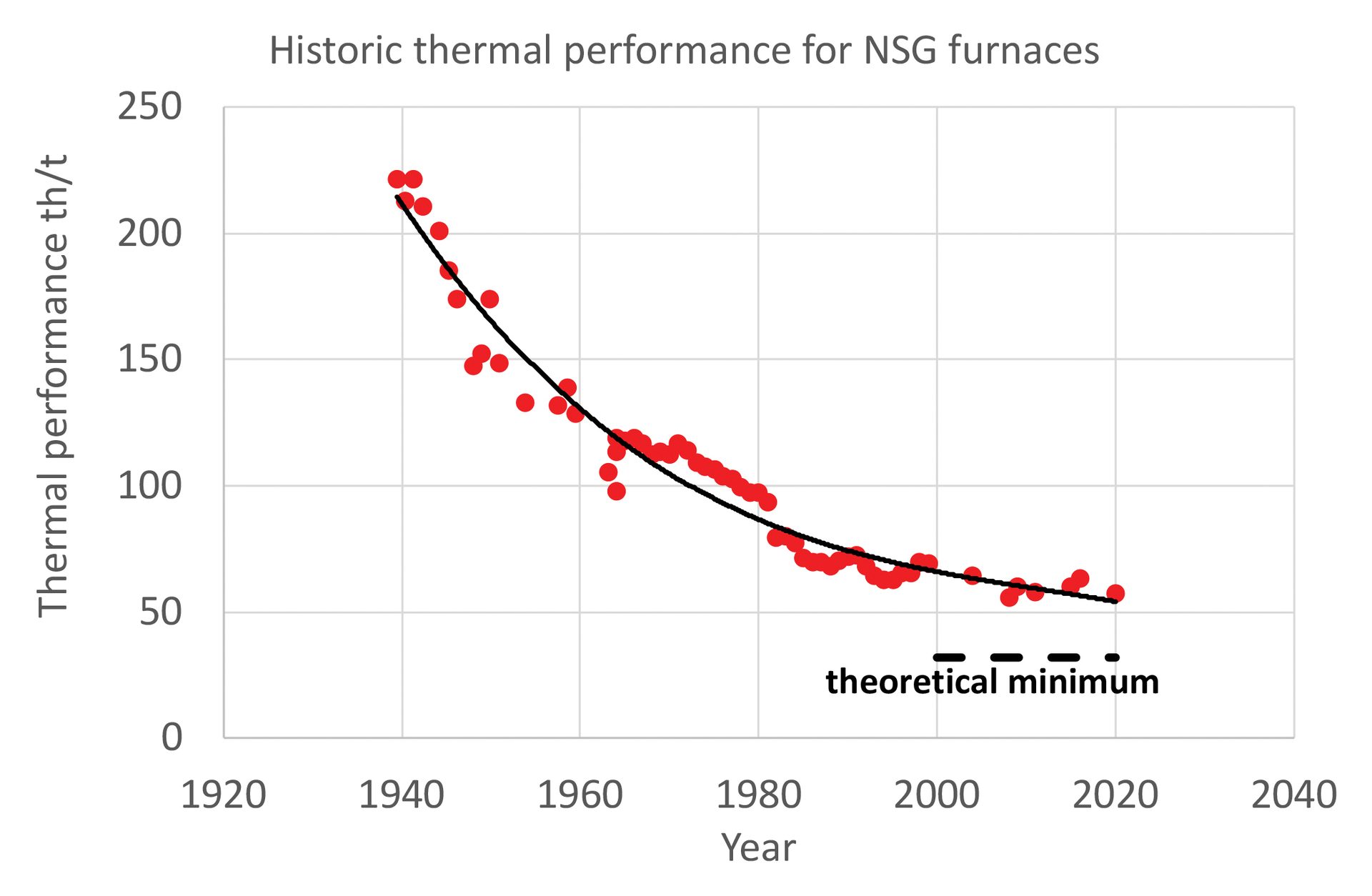
Figure 1. Historical thermal performance (therms per metric ton) for NSG glass furnaces. One therm is 100,000 BTU, or the approximate energy content of 100 cubic feet of natural gas at standard temperature and pressure.
Credit: NSG
Biofuels
For furnaces that use natural gas, the most straightforward path to decarbonizing thermal energy is to switch to a “carbon-neutral” gas.
The methane in natural gas is produced by thermogenic decomposition of fossil organic matter. In contrast, biogenic methane, or biogas, is produced by the anaerobic decomposition of organic material. It is considered carbon neutral because the CO2 emitted to the atmosphere during combustion is the same that was taken in by photosynthesis from the source plant material. Important producers of biogas are landfills, wastewater treatment facilities, and large-scale livestock operation manure digesters. The U.S. also has some stand-alone digesters that process food and yard waste.
Raw biogas is up to 60 vol.% methane with the remainder consisting of mainly CO2 and small amounts of hydrogen sulfide. Removal of moisture and sulfur allows the biogas to be used on-site to generate electricity in reciprocating engines or microturbines. Additional treatments can make a gas of at least 90% methane (referred to as renewable natural gas or RNG) that can directly replace fossil-based natural gas in pipelines.
Early trials appear promising. For example, Saint-Gobain Glass reported the successful one-week operation of its float furnace in 2022 in Aniche, France, using 100% biogas.5
While it is technically feasible to use biogas, potential hurdles for increasing its use include a lack of sufficient volume and competition with on-site electricity generation and its use as a transportation fuel. If future RNG production increases to quantities that allow it to be injected into existing natural gas pipelines, that will improve the delivery of RNG to users, but it could be difficult to track which facility can apply this method to their decarbonization accounting.
Liquid biofuels such as bio-oil (also called biodiesel) and ethanol are currently derived from corn and soy with a limited supply of biodiesel deriving from used food oils. Ethanol is not a feasible glass furnace fuel, but bio-oil could be used.
Trials have been completed by Encirc and Pilkington using fatty acid methyl ester derived from waste animal and vegetable oil. Bio-oil was burned at the Encirc Derrylin factory in Northern Ireland for an extended trial producing low-carbon bottles. Pilkington’s St. Helens (U.K.) float furnace was fired on 100% bio-oil for four days with no impact on glass quality. Waste-derived bio-oil offers a potential source, but obtaining the quantities needed to continuously supply a furnace is an issue.
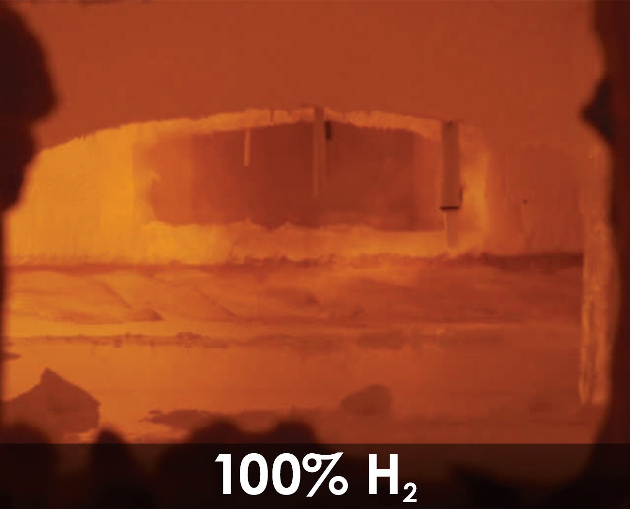
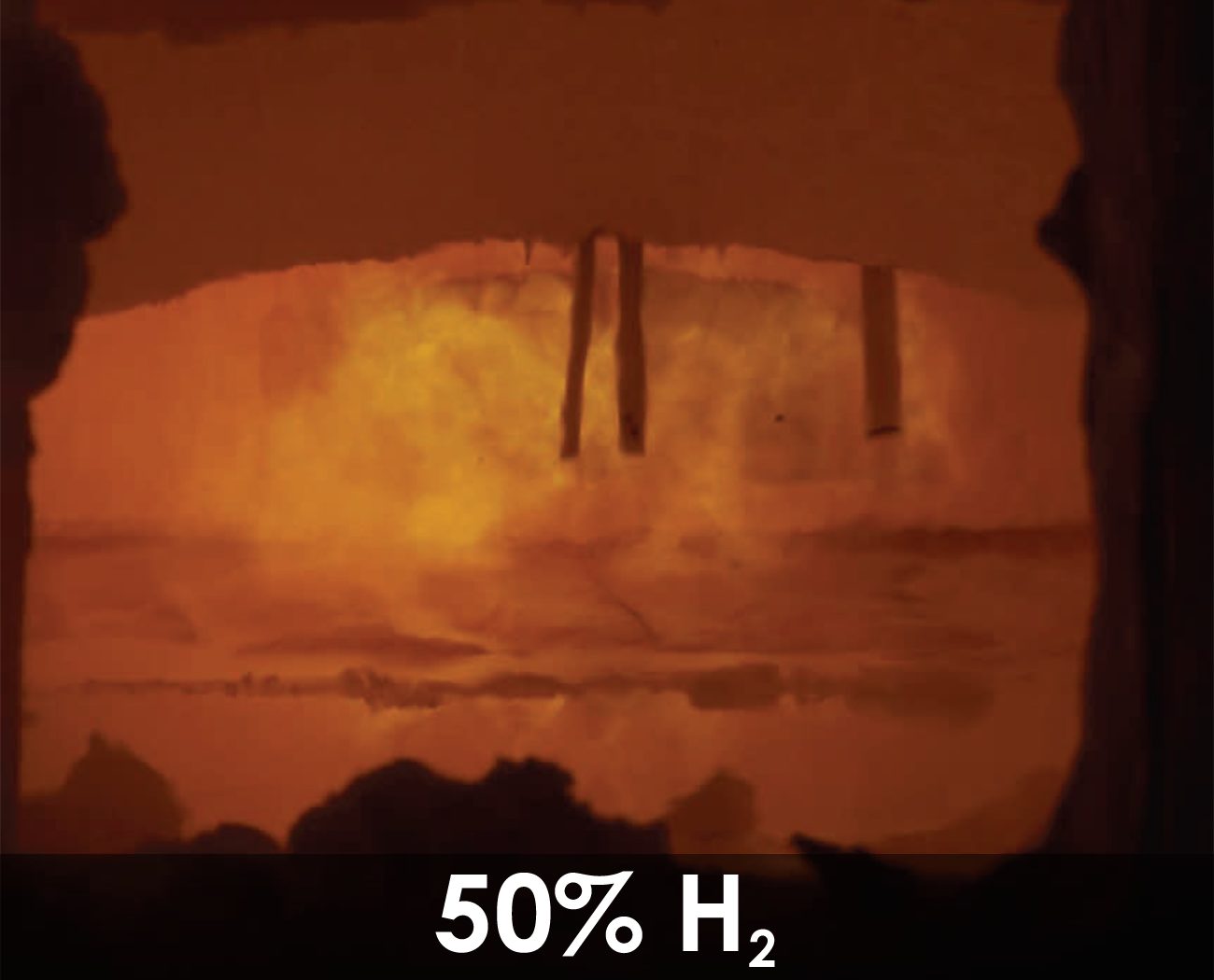
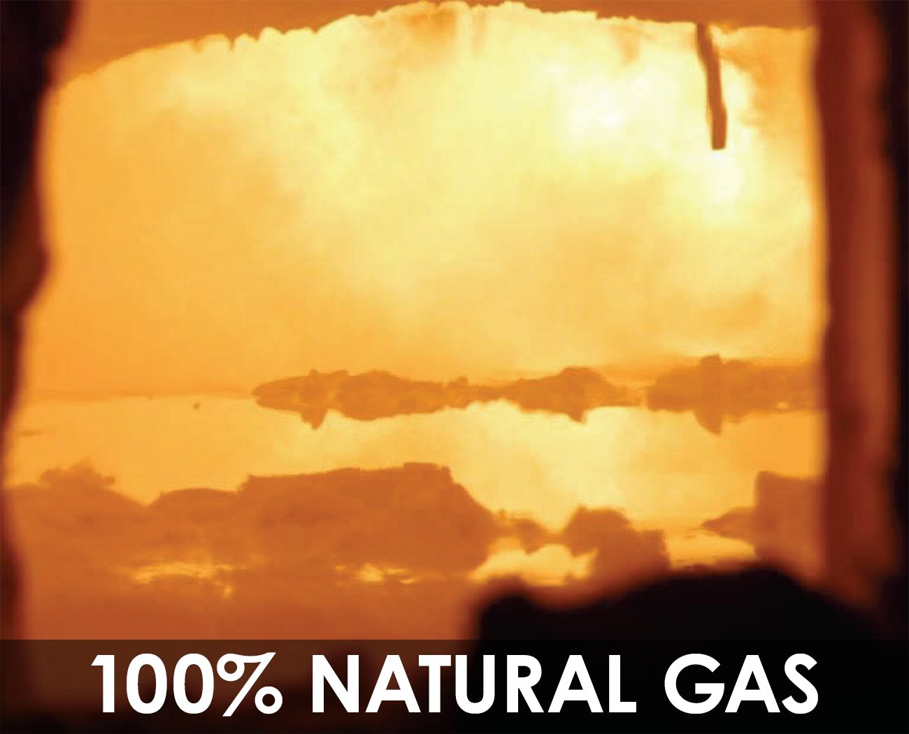
Figure 2. Glass melting trial in a flat glass furnace using a single port burner showed glass melting in progressively hydrogen-rich fuel mixes starting with 100% natural gas, 50% each natural gas and hydrogen, and 100% hydrogen.
Credit: Pilkington
Bio-syngas
Synthesis gas (syngas) is a combustible mixture of hydrogen and carbon monoxide generated by heating a solid fuel in a low-oxygen environment. Syngas is currently manufactured from fossil fuels to produce hydrogen (see following section) for ammonia and methanol. But syngas can also be made from biomass, including municipal solid waste. A feasibility study was completed in 2022 for a syngas facility at Pilkington’s St. Helens float facility in collaboration with KEW Technology (Birmingham, U.K.).6 Furthermore, synthetic liquid fuels can be made from syngas using the Fischer-Tropsch process, which was developed almost a century ago by Germany during WWII to synthesize liquid fuels from coal.
Green hydrogen
Hydrogen is a highly combustible gas and emits no CO2 when burned. Hydrogen on Earth is extremely reactive and, therefore, is usually tightly bound up in compounds such as water, biomass, and hydrocarbons. Separating hydrogen from its compounds takes energy, so it is considered an energy carrier similar to electricity. The exception is the recent discoveries of natural hydrogen deposits in subsurface reservoirs that may contribute to our supply of the gas.7
Hydrogen is an important industrial gas used for oil refining, ammonia production (fertilizer), steelmaking, and methanol synthesis. Most hydrogen is produced from natural gas through steam methane reformation (SMR), which separates the carbon and hydrogen to make syngas. Hydrogen can also be generated by electrolysis of water, but so far water electrolysis has been much more expensive than SMR.
Hydrogen can play an important role in industrial sectors with emissions that are difficult to remove as long as it comes from a low-carbon source. Hydrogen is graded based on its carbon intensity: “gray” hydrogen is from SMR, “blue” hydrogen is produced when the carbon removed during SMR is captured and geologically stored, and “green” hydrogen is from electrolysis of water using electricity sourced from zero-carbon generators. The ideal goal is to transition to green hydrogen.
Using hydrogen in a glass furnace is feasible. Pilkington demonstrated in 2021 that a flat glass furnace can be used to effectively melt glass (Figure 2, above). A single port of the furnace was converted to allow a blend of hydrogen and natural gas to be fired. In this instance, “gray” hydrogen was used because low-carbon “green” hydrogen is currently not available. Trials that progressively increased the volume fraction of hydrogen in the fuel mix demonstrated that effective melting can be achieved using 100% hydrogen. Of note, at high hydrogen percentages, the flames in the furnace become effectively invisible.
The low energy density of hydrogen means that the volume of fuel increases three times for the same energy input. The hotter flame temperatures also lead to an about 20% increase in NOx generation, which is less than predicted by computational fluid dynamics modeling.
In the U.S., current infrastructure to generate and deliver gray hydrogen clusters around petrochemical hubs, such as the Gulf Coast. However, the U.S. government has signaled its support of low-carbon hydrogen through the passage of two recent bills.
- The Investment and Jobs Act of 2021 contains $9.5 billion funding for hydrogen, including $8 billion for building a hydrogen hubs infrastructure. The hydrogen hubs are still in the competition phase, and the Great Lakes Clean Hydrogen coalition was encouraged by the Department of Energy to submit a full application. The proposed hub near Toledo, Ohio, would generate hydrogen by electrolysis using nuclear power-sourced electricity and create a distribution system that can provide for nearby industrial users, including several glass producers.
- The Inflation Reduction Act of 2022 provides a 10-year production tax credit for “clean hydrogen” production facilities, which is a sliding scale dependent on carbon emissions used to generate the gas.
Strong government backing could provide the market impetus to develop green hydrogen, and glass plants adjacent to hydrogen hubs will be best suited to initially adopt hydrogen fuel to replace natural gas.
There are other technical hurdles, such as the development of enough efficient electrolyzers. Additionally, the glass industry will need to compete with other industries that use hydrogen, such as ammonia/fertilizer production and steel manufactures that are using direct reduction methods. Finally, it is more efficient to use low-carbon electricity directly to melt glass where possible rather than use it to generate hydrogen.
“Hydrogen can play an important role in industrial sectors with emissions that are difficult to remove as long as it comes from a low-carbon source.”
Low-carbon electrification
Some existing glass furnaces use only electricity to provide process energy. These furnaces are mostly cold-top vertical melters used to produce 5 to 80 tpd.
An electric glass melter is more thermally efficient than a fuel-fired system, and there are no direct emissions related to fuel combustion. They are simpler because there is no need for regenerators or recuperators and, therefore, are less costly to build.8 However, electric furnaces have much shorter times between rebuilds than gas furnaces, cannot handle large proportions of cullet, and have practical limitations to scaling to the capacity of gas-fired furnaces.9
Some gas-fired furnaces use electric boosting to add energy directly into the melt to increase pull rate and improve glass quality. For conventional horizontal, combustion fired furnaces, electric boost has a practical limit of providing 15% of the energy requirement, but it can reach 35% in some situations.9
Newer hybrid melter designs maintain a hot top with fuel combustion, and submerged electrodes can increase electrification; however, it cannot fully remove the need for fuel. Manufacturers of new hybrid furnaces claim they can operate with as much as 80% of the energy coming from electricity. Saint-Gobain Glass is developing a hybrid electric pilot-scale furnace with AGC in Barevka, Czech Republic.10 They will use data from these pilot tests to design a full-scale furnace, as well as repair a float furnace with such a design.
Fiberglass manufacturing presents particular challenges toward electrification. According to Jonathan McCann, principal materials engineer at Johns Manville (Littleton, Colo.), glass fiber melting with only electricity would be difficult for reasons associated with glass quality requirements, refractory selection, and the low alkali (R2O) content of the composition. So, the reinforcement fiberglass industry has taken a more gradual approach to increasing the proportion of electric boost energy to combustion energy.
In the insulation fiberglass segment, electric melters are well established as an effective way to melt insulation fiberglass; however, a significant amount of fossil fuels are typically used for both the fiberization and the curing of fiberglass product. For the home insulation industry, elimination of these sources of carbon presents the bigger technical challenge.
If a glass producer wanted to fully decarbonize their product by moving to electrical melters, it would still need to be able to have access to zero-carbon electricity. The CO2 indirectly emitted from electric melting is a function of the mix of power generation sources supplying the power grid. Powerplants using coal and natural gas emit CO2 directly into the atmosphere while hydro, nuclear, solar, and wind do not.
In the U.S. in 2021, approximately 0.39 metric tons of CO2 was emitted for each MWh of electricity generated. In other words, a ton of glass from an electric melter in the U.S. indirectly emits almost 1 metric ton of CO2 (on the basis of 2.4 MWh per ton of glass produced).1 This statistic can differ by region or state. For example, a MWh of electricity in Washington emits 0.1 metric tons of CO2 while Kentucky plants emit 0.80 metric tons of CO2 for the same amount of output. These values reflect the large proportion of hydroelectricity in Washington and the dominance of coal in Kentucky. Scope 2 GHG emissions for electricity can be calculated based on region in the United States, so location does matter.
On-site solar panels or wind turbines cannot supply the power and reliability needed, and manufacturers generally prefer to buy green power rather than go into the low-carbon energy conversion business. Reducing the CO2 emission factor of delivered electricity toward zero is not easily controlled by a manufacturer. Moving operations to a region that currently has or is trending toward a high proportion of low-carbon generating electricity would theoretically be possible, but it is not practical for many reasons, including issues such as access to raw materials, nearness to end-user customers, and the ethics of abandoning manufacturing plants.
“An electric glass melter is more thermally efficient than a fuel-fired system...[but there are] practical limitations to scaling to the capacity of gas-fired furnaces.”
Carbon capture, utilization, and storage
Carbon capture, utilization, and storage (CCUS) refers to capturing CO2 from an emission source and transporting it to where it can be used or injected underground for long-term storage.
Carbon capture from a point source such as a glass furnace can be done either before or after combustion. Pre-combustion capture would use SMR to generate blue hydrogen from natural gas and route the separated CO2 elsewhere. Post-combustion capture of CO2 in an air-fuel burner requires passing the flue gas through an amine absorber that can capture up to 90% of the CO2. The amine solution is then sent to a heater to release the concentrated CO2 for compression and transport.
One challenge with glass furnaces is the relatively high levels of NOx and SOx, which are not compatible with amine-based capture technologies. Additional waste gas cleaning (i.e., above that required to meet emissions regulations) is required to use these technologies. Oxy-fuel furnaces do not need an amine absorber system; however, water vapor must be removed from the flue gas before the concentrated CO2 is ready for use or storage.
Other technologies, more amenable to glass furnace waste gas compositions, are also being investigated. Pilkington is undertaking trials with C-Capture Ltd. using their solvent-based technology at their plant in St. Helens, U.K.11
The process of injecting CO2 underground is already used by petroleum producers for tertiary or enhanced oil recovery of light and medium crude, where CO2 injected into a well pushes the oil toward a production well. The irony of this process is that it increases our ability to extract and burn fossil fuels, thereby increasing atmospheric GHG. However, it does demonstrate that the CO2 can be collected, transported, and injected into geologic storage. Currently about 5,000 miles of CO2 pipelines exist in the U.S., mostly Texas, for enhanced oil recovery.
Other geologic storage options include deep saline aquifers, depleted natural gas and oil basins, and deep, unmineable coal seams. DOE estimates the U.S. has geologic CO2 storage capacity of between 2.6 trillion to 22 trillion metric tons with the majority of that in deep saline aquifers.12
As of 2022, one U.S. facility, an Archer Daniels Midland ethanol plant in Decatur, Ill., was injecting CO2 into a deep saline aquifer.9 Equinor, the Norwegian energy company, has been testing CO2 injection underneath the sediments of the North Sea. This process is not the same as deep ocean sequestration, which involves pumping CO2 at thousands of meters below the water surface. Deep ocean sequestration has several inherent problems. The CO2 will eventually come back to the sea surface, and it lowers the seawater pH due to increased carbonic acid.
For CCUS to be technically feasible for a glass furnace, it should be an oxy-fuel system so that the expense of an amine absorber is not needed, and the plant should be located adjacent to a CO2 pipeline. This rapidly developing technology area has not yet been specifically proven in the glass industry, but it shows promise as it matures.
SIDEBAR
Carbon offset credits
Carbon offsetting means reducing or removing GHGs in one place to compensate for an entity’s emissions from somewhere else. A single carbon offset credit represents a metric ton of CO2 or equivalent GHG that has been reduced, avoided, or removed from the atmosphere. The credits can be certified by governments or an independent certification body and can be traded through a carbon market.
The global carbon offset market is valued at approximately $1 billion and is growing as companies attempt to reduce their carbon footprints. However, not all offset credits are equal. Some “nature-based” credits are derived from projects that estimate emission reductions from avoided land use or development, such as conserving an area slated for timber harvest. For example, the owner of a parcel of rainforest slated for clearcutting is paid not to harvest the trees. Calculation of the avoided emissions will depend on the assumptions and the model used. Forest-based credits are currently one of the most common available.
High-quality offsets need to be additional (would not have occurred without a specific associated project), permanent, accurately estimated or quantified, and not cause significant social harm. One criticism of offset credits associated with new wind and solar projects is that they do not pass the additionality test. That is, they would be built without the need for offset credits because they are cost-competitive without them, although they may be the lowest cost option for companies that want to offset their emissions. Credits associated with carbon capture and geologic storage result in quantifiable reductions in GHG emissions, but they will cost significantly more.
Because of the diversity of available offset products, it can be difficult and time-consuming to assess the quality of offsets, particularly in the voluntary market. In the compliance market, government agencies (such as the California Compliance Offset Program) tend to be in charge of verifying the quality of offsets.
Carbon offsets can be a tool to help a company to meet its emission reduction goals, but it cannot be the primary strategy. A manufacturer should first reduce GHG emissions on-site prior to resorting to offsets to obtain zero emissions.
One potential way to reduce carbon emissions from soda ash is to use the Solvay process with CO2 derived from a CCUS stream rather than calcined limestone.
Decarbonizing raw materials
Approximately 20% of CO2 released from a typical soda lime silica glass comes from the reaction of the raw materials. Sodium carbonate (soda ash), limestone (calcium carbonate), and sometimes dolomite (a mixed calcium and magnesium carbonate) comprise the main components of a soda lime silica glass batch. These materials are low cost and plentiful. However, when these carbonate minerals are heated and the carbonate decomposes, CO2 is released into the atmosphere.
It will be difficult to replace limestone and dolostone as the primary source of calcium and magnesium in glass given the widespread deposits and low cost. Calcium oxide, or quicklime, is made from burnt limestone, which only displaces the location of CO2 emission; plus, quicklime hydrates and poses human health hazards.
Most U.S. glass manufacturers use Wyoming trona (Na2Co3–2NaHCO3–3H2O) as the source of soda ash. Trona, by way of a glass melting furnace, transfers carbon from the ground into the atmosphere. Synthetic (Solvay) soda ash is made by reacting sodium chloride with CO2 derived from calcining limestone, so that the CO2 emissions at the glass plant originated in limestone; this process also transfers carbon from the ground to the atmosphere.
One potential way to reduce carbon emissions from soda ash is to use the Solvay process with CO2 derived from a CCUS stream rather than calcined limestone. If the process is coupled with waste brine from seawater desalinization, the resulting soda ash is the product of two waste streams.13 This approach is in the conceptual stage but could be brought to market with sufficient financial incentives.
As previously discussed, increasing the amount of cullet in a batch is the most straightforward way to reduce the CO2 emissions associated with raw materials, and it also reduces melting energy and reduces waste streams. In the U.S., post-consumer container glass cullet is used mainly in container glass and discontinuous insulation fiber glass. Both of these glass sectors can use up to 80% of cullet in the batch. Flat glass manufacturers cannot use container cullet but can use flat glass cullet, if available.
The major hurdle for increasing the amount of cullet is that only about a third of glass containers in the U.S. are recycled, and that rate has remained flat for decades.14 Flat glass manufacturers can use pre-consumer cullet, but post-consumer cullet is essentially nonexistent because of the cost to recover flat glass during building and vehicle demolition in the U.S. (According to Saint-Gobain, the EU is working on post-consumer cullet adoption.) Furthermore, flat glass generally has higher quality standards than container glass and a lower threshold for impurities.
Conclusions
Decarbonization of glass manufacturing is feasible through multipronged strategies. Energy efficiency measures should continue, which includes an increase of cullet use where possible. The most important step is the implementation of low-carbon fuels and electrification. Future glass melters will be hybrid systems that use low-carbon electricity boosting coupled with low-carbon fuels, such as green hydrogen. CCUS is possible, but it would need an oxy-fuel furnace located near a CO2 pipeline and transmission system. Decarbonization of raw materials is perhaps the most challenging part and should initially come from increased use of cullet. Emissions from soda ash could be reduced by using CCUS-derived Solvay material if that is ever developed. High-quality carbon sequestration credits (see sidebar: Carbon offset credits) can be used to offset emissions that cannot be feasibly achieved by the glass manufacturer.
The deep decarbonization of glass manufacturing can be achieved, but it will take time and changes to the current system. It will also require considerable funds and a mix of government support, incentives, and possibly regulations. If these goals are reached, we can enjoy our evening drink from a zero-carbon bottle.
Acknowledgements
Andrew Keeley of Pilkington made significant contributions to this paper. The author would also like to thank Anna Herring at the University of Tennessee Knoxville for help with the current state of CCUS.
About the author:
Christopher Sinton is senior scientist at Integral Consulting Inc. Contact Sinton.
*Assumes a 300 tpd air-fuel furnace with electric boost and 50% cullet emitting 332 kg CO2 per metric ton glass (Reference 1) and beer and wine bottles of 180 g and 500 g, respectively. This estimate does not include emissions associated with a bottle after it leaves the plant.
